Pneumatic impact riveting machine

A technology of riveting machine and riveting head, applied in the field of riveting machine, to achieve the effects of convenient operation, overcoming adjustment difficulties and high synchronization

Inactive Publication Date: 2014-06-18
SHANDONG LEDE CNC MACHINERY
View PDF5 Cites 2 Cited by
  • Summary
  • Abstract
  • Description
  • Claims
  • Application Information

AI Technical Summary

Problems solved by technology

Then the riveting cylinder drives the swing arm and the lever to complete the riveting process

Method used


Image

  • Pneumatic impact riveting machine
  • Pneumatic impact riveting machine
  • Pneumatic impact riveting machine

Examples


Embodiment Construction

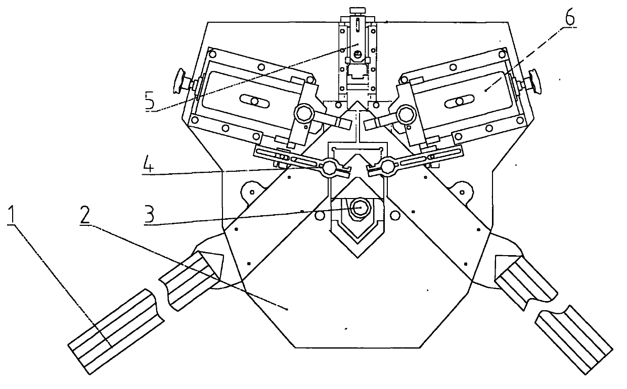
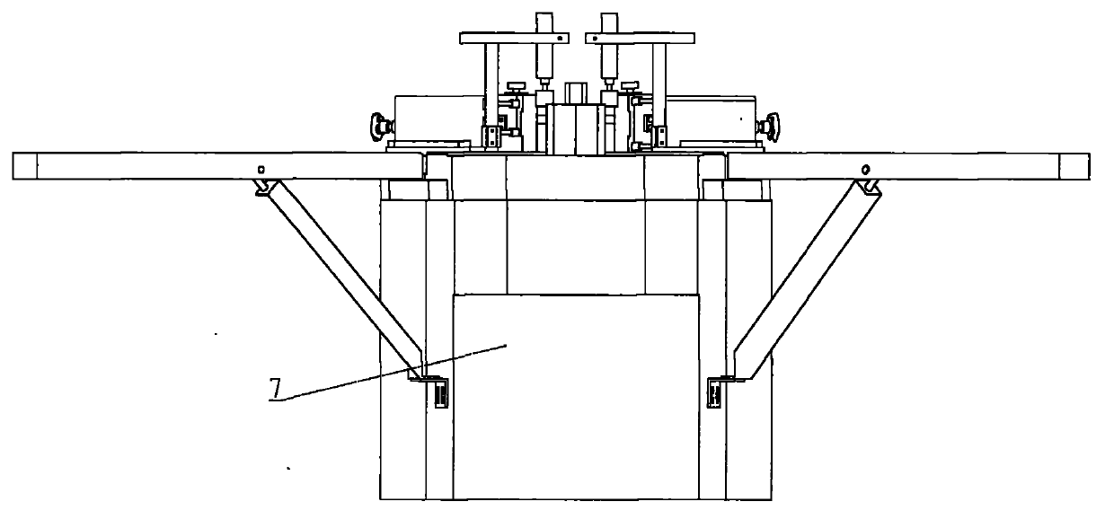
[0022] Such as figure 1 , figure 2 As shown, a pneumatic riveting machine includes a supporting device 1, a worktable 2, a main positioning device 3 that can be lifted and translated, a pressing device 4, an adjustable rear positioning device 5, an adjustable corner extrusion head 6 and a body 7 . The two adjustable rivet heads 6 complete work forward and work retreat along the guide device on the workbench 2 under the action of the same cylinder, so that the synchronization and stability of the two rivet heads are higher.

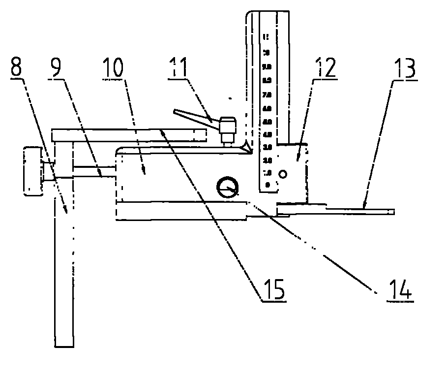
[0023] Such as image 3 As shown, the adjustable rear positioning device 5 includes: a rear positioning slide 10, a strong magnetic slider 12 adjusted up and down along the rear positioning slide 10, a rear positioning block 13 fixed on the slide 12, and adjustable by locking The fixed shaft 14 locked by the handle 11; the adjustment plate 8 fixed on the workbench 2, the adjustment plate 8 is provided with an adjustment screw 9, the threaded end of the...


PUM


Abstract

The invention relates to a pneumatic impact riveting machine, which comprises a machine body and a workbench positioned on the machine body, wherein left and right symmetric travel-adjustable impact riveting heads, an external positioning device of which the front and rear positions are adjustable, a cylinder for driving the impact riveting heads to work, a main positioning lifting guide rail, a clamping device and a main positioning guide plate are arranged on the workbench. The pneumatic impact riveting machine also comprises a main positioning device, wherein a main positioning head can move up and down, and can move along a horizontal guide rail; a main positioning lifting sliding seat is arranged on the main positioning lifting guide rail; a perpendicular cylinder and a horizontal cylinder are arranged on the main positioning lifting sliding seat; a piston rod of the perpendicular cylinder is connected with a lifting sliding seat; a horizontal sliding seat is also arranged on the lifting sliding seat; one end of a piston rod of the horizontal cylinder is fixedly arranged on the horizontal sliding seat; a mounting seat with a main positioning block is arranged on the horizontal sliding seat. The pneumatic impact riveting machine has the advantages of high positioning speed, easiness in operation, high machining speed, high forming quality and the like.

Description

technical field [0001] The invention relates to a riveting machine, in particular to a pneumatic riveting machine. Background technique [0002] At present, profile riveting equipment is generally divided into two categories, one is gas-hydraulic booster transmission, which is powered by compressed air and gas-hydraulic booster cylinder; the other is hydraulic transmission, which is powered by pressure oil provided by a hydraulic station. Since the gas-hydraulic booster cylinder supplies oil to the two impact riveting cylinders at the same time, the synchronization is poor, and it is difficult to achieve the balance of the force of the two impact riveting knives; the consistency of hydraulic transmission power is good, but the two impact riveting knives are integrated It is very difficult to adjust the transmission of power, and it is very easy to cause the asynchronous impact of the riveters on both sides, and the noise pollution is very serious. The above two types of riv...

Claims


Application Information

Patent Timeline
Patent Type & Authority Applications(China)
IPC IPC(8): B21D39/00
Inventor 苗青晓王丛丛
Owner SHANDONG LEDE CNC MACHINERY
Why Eureka
Try Eureka