Hydraulic-drive automatic feeding system

An automatic feeding and hydraulic technology, which is applied in the direction of fluid pressure actuators, presses, servo motors, etc., can solve the problem that the processed parts should not be realized manually

Inactive Publication Date: 2014-06-18
南京恒誉名翔科技有限公司
View PDF0 Cites 1 Cited by
  • Summary
  • Abstract
  • Description
  • Claims
  • Application Information

AI Technical Summary

Problems solved by technology

[0002] In the pressing process of the mold, considering the labor intensity and other reasons, it is not suitable to do it manually in the process of placing the processed parts

Method used


Image

  • Hydraulic-drive automatic feeding system
  • Hydraulic-drive automatic feeding system
  • Hydraulic-drive automatic feeding system

Examples


Embodiment Construction

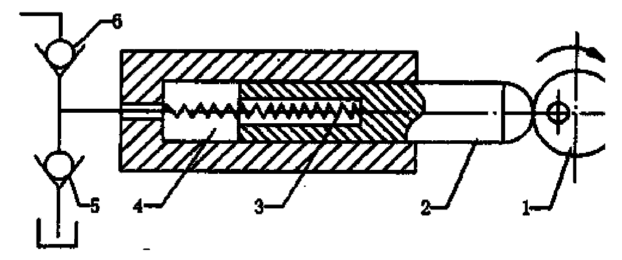
[0019] By connecting a one-way valve 6 in series to the circuit, the oil inlet circuit and oil return circuit are cut off during fast forwarding, so as to solve the problem that the oil inlet circuit and oil return circuit are connected to each other during fast forwarding of the slide table, and the pressure cannot be established. Hydraulic change. A hydraulic sequence valve 8 is connected in series on the oil return road to prevent the oil from returning to the oil tank during the fast-forward stage, which solves the problem that the oil return line is connected to the oil tank when the slide table is fast forwarding, and the differential connection of the hydraulic cylinder cannot be realized. Adding a check valve 1 at the outlet of the electro-hydraulic reversing valve solves the problem that the oil in the system flows to the oil tank when the system stops working, causing air to enter the system and affecting the stability of the sliding table movement. A pressure relay ...


PUM


Abstract

Disclosed is a hydraulic-drive automatic feeding system. A mold press automatic feeding system serves as an important constitution portion of the mold press, and the reasonability and the feasibility of the design guarantee the normal operation of the whole system. During mold pressing, the automatic feeding system replaces labor to complete feeding, so that the labor intensity and the labor danger coefficient are greatly reduced, and the work efficiency is greatly improved. The hydraulic system meeting particular requirements of the automatic feeding system is designed after synthesizing advantages and disadvantages at home and abroad, and scientific and rigorous calculation and analysis are performed on all parts of the system, so that the system feasibility is guaranteed theoretically. Started from the environment protection, the system oil pollution problem is analyzed, and corresponding solutions are put forward, so that the mold press is developed towards the green direction.

Description

technical field [0001] This product is a hydraulic feeding system. Background technique [0002] In the pressing process of the mold, considering the labor intensity and other reasons, it is not suitable to implement the process of placing the processed parts manually. Compression molding machine from The automatic feeding system can replace the manual process. Safety, work efficiency, etc. are greatly improved. Labor intensity is greatly reduced. Contents of the invention [0003] The object of the present invention is to provide a hydraulic transmission device most suitable for feeding systems. [0004] The purpose of the present invention is achieved like this: [0005] A hydraulic system is mainly composed of fuel tank (1), oil filter (2), hydraulic pump (3), overflow valve (4), on-off valve (5), throttle valve (6), reversing valve (7) , hydraulic cylinder (8) and the oil pipe (9) piston (10) and workbench (11) connecting these components. [0006] It works lik...

Claims


Application Information

Patent Timeline
Patent Type & Authority Applications(China)
IPC IPC(8): B30B15/30B30B15/16F15B11/02F15B13/02
Inventor 王瑛李忠喜
Owner 南京恒誉名翔科技有限公司
Why Eureka
Try Eureka