Engine cooling system for vehicle and control method of the same

An engine cooling and control method technology, which is applied to the cooling of the engine, the control of the coolant flow, the control device of the cooling device, etc., can solve the problem of the decrease of the coolant flow speed of the heating pipeline, the increase of the fuel consumption, the poor effect, etc. problems, to achieve the effect of optimized flow speed, improved operational reliability and efficiency, and simple layout

Inactive Publication Date: 2014-06-18
HYUNDAI MOTOR CO LTD
View PDF6 Cites 12 Cited by
  • Summary
  • Abstract
  • Description
  • Claims
  • Application Information

AI Technical Summary

Problems solved by technology

[0005] Also, while there is a way to install an ATF (Automatic Transmission Fluid) heater on the preheat circuit of the engine cooling system, it adds cost and is not very effective
[0006] In addition, when the ATF heater is applied to reduce the friction of the automatic transmission through its rapid warm-up, the coolant flow speed of the heating line decreases, the fuel consumption increases due to the decrease in the heat supplied from the engine to the heater, and must Install a separate bypass channel

Method used


Image

  • Engine cooling system for vehicle and control method of the same
  • Engine cooling system for vehicle and control method of the same
  • Engine cooling system for vehicle and control method of the same

Examples


Embodiment Construction

[0034] Reference will now be made in detail to various embodiments of the invention, examples of which are illustrated in the accompanying drawings and described below. While the invention will be described in conjunction with exemplary embodiments, it will be understood that present description is not intended to limit the invention to those exemplary embodiments. On the contrary, the invention is intended to cover not only the exemplary embodiments, but also various alternatives, modifications, equivalents and other embodiments, which may be included within the spirit and scope of the invention as defined by the appended claims.

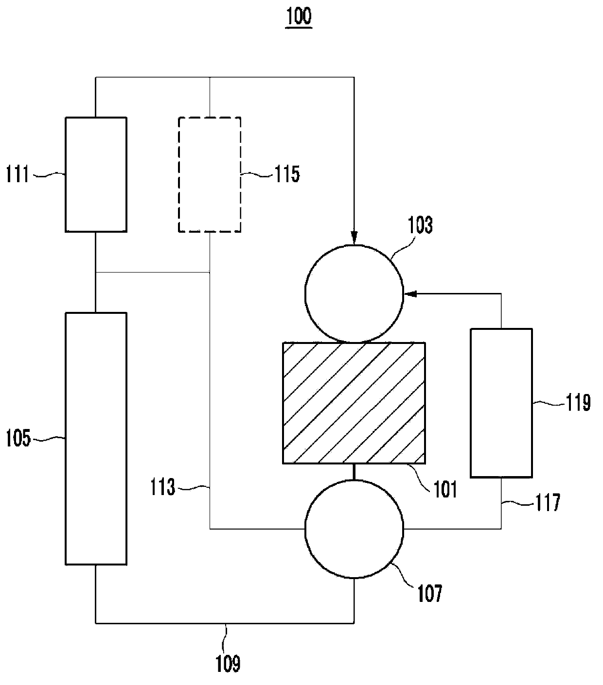
[0035] figure 1 is a block diagram of an engine cooling system for a vehicle according to various embodiments of the present invention.

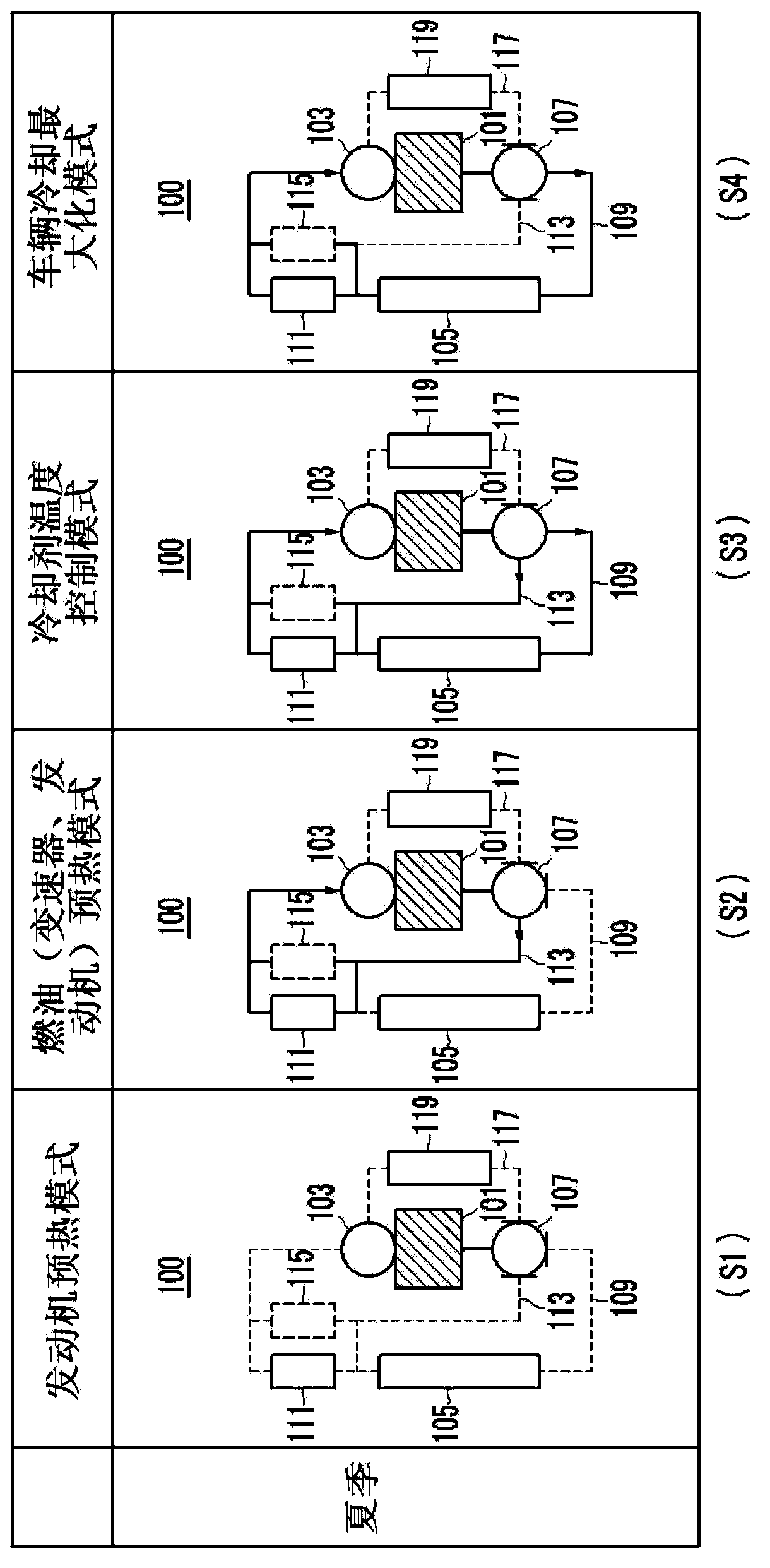
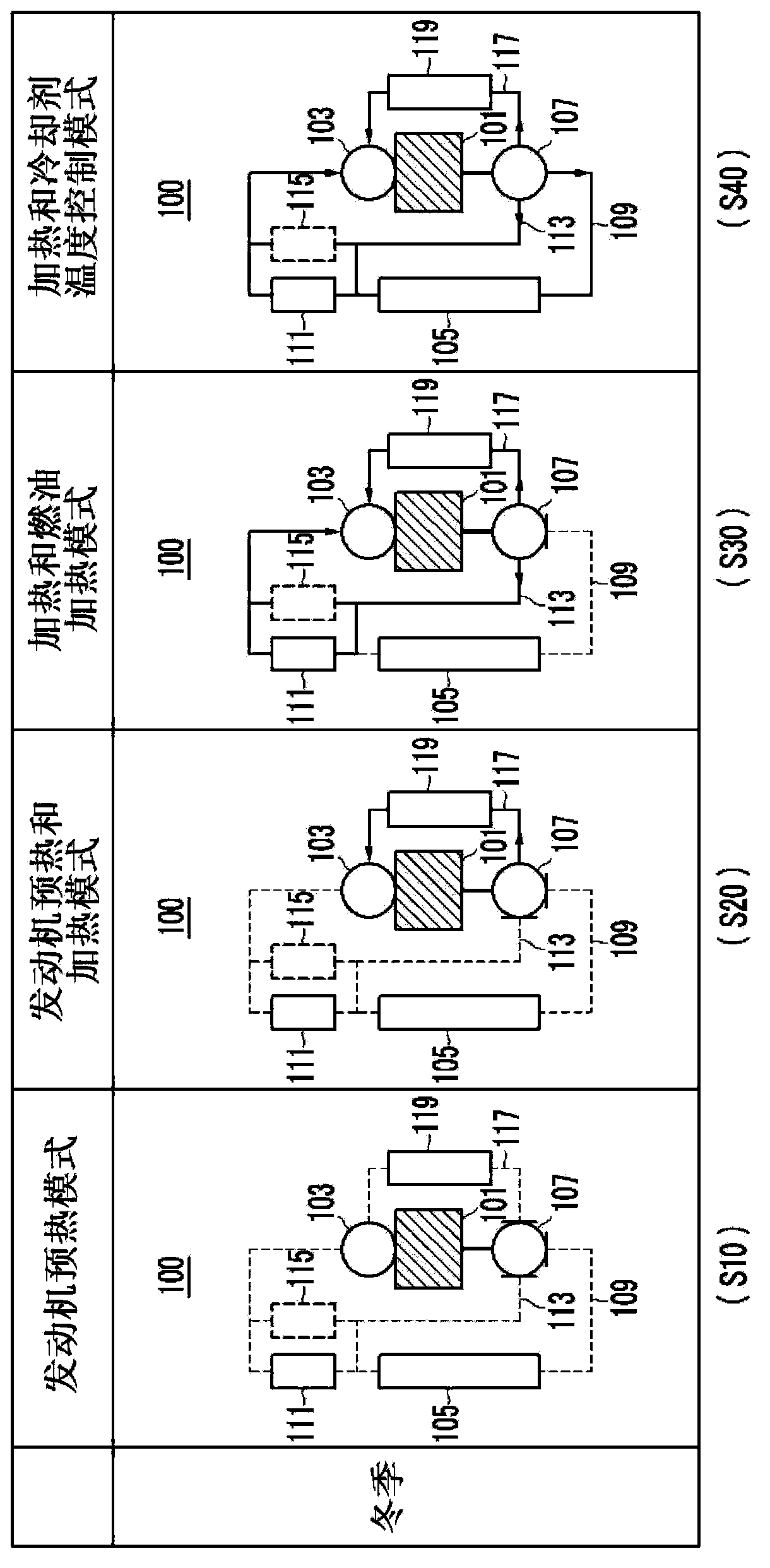
[0036] Referring to the drawings, an engine cooling system 100 for a vehicle according to various embodiments of the present invention effectively uses waste heat of an engine 101, and controls a flow direction ...


PUM


Abstract

An engine cooling system for a vehicle includes a water pump disposed to supply an engine with a coolant and a radiator disposed to cool heated coolant of the engine by exchanging heat with outside air. The system may include: a control valve that is disposed at one side of the engine to control flow rate and flow passage of coolant; a first passage that connects the control valve with the radiator and connects the radiator with the water pump; a TOC that is disposed between an outlet of the radiator and the water pump to be connected through the first passage; a second passage that connects the TOC with the control valve and directly supplies the TOC with the coolant exhausted from the engine; and a heater that is disposed in a third passage that bypasses the engine to connect the control valve with the water pump.

Description

[0001] Cross References to Related Applications [0002] This application claims priority from Korean Patent Application No. 10-2012-0147801 filed on December 17, 2012, the entire contents of which are hereby incorporated by reference for all purposes. technical field [0003] The present invention relates to an engine cooling system and a control method for a vehicle to control flow direction and coolant flow rate to provide optimum cooling conditions. Background technique [0004] Coolant temperature is controlled using a motorized water pump or using an electronic thermostat utilizing an electronic heater. [0005] Also, while there is a way to install an ATF (Automatic Transmission Fluid) heater on the preheat circuit of the engine cooling system, it adds cost and is not very effective. [0006] In addition, when the ATF heater is applied to reduce the friction of the automatic transmission through its rapid warm-up, the coolant flow speed of the heating line decreases,...

Claims


Application Information

Patent Timeline
Patent Type & Authority Applications(China)
IPC IPC(8): F01P3/00F01P7/14
CPCF01P7/165F01P2037/02F01P2060/045F01P2060/18F01P7/16F01P3/18F01P3/20F01P11/08
Inventor 吴昌锡
Owner HYUNDAI MOTOR CO LTD
Why Eureka
Try Eureka