
Spiral centrifugal pump

A technology of spiral and spiral impeller, which is applied in the field of spiral sand and gravel pump equipment, can solve the problems of material damage, insufficiency, winding and blockage, etc., and achieve the effect of improving the technological level.

Inactive Publication Date: 2014-06-18
南京恒誉名翔科技有限公司
View PDF0 Cites 1 Cited by
  • Summary
  • Abstract
  • Description
  • Claims
  • Application Information

AI Technical Summary

Problems solved by technology

[0002] Although the existing various impurity pumps have good performance in pumping mixed liquid containing impurities and particles, due to the limitation of the structure of the pump body, winding and clogging failures often occur during operation, which seriously damages the materials, and cannot be used to pump long fibers, Large particle size solids and undamaged materials are far from meeting the needs of multiple industries

Method used


Image

  • Spiral centrifugal pump

Examples


Embodiment Construction

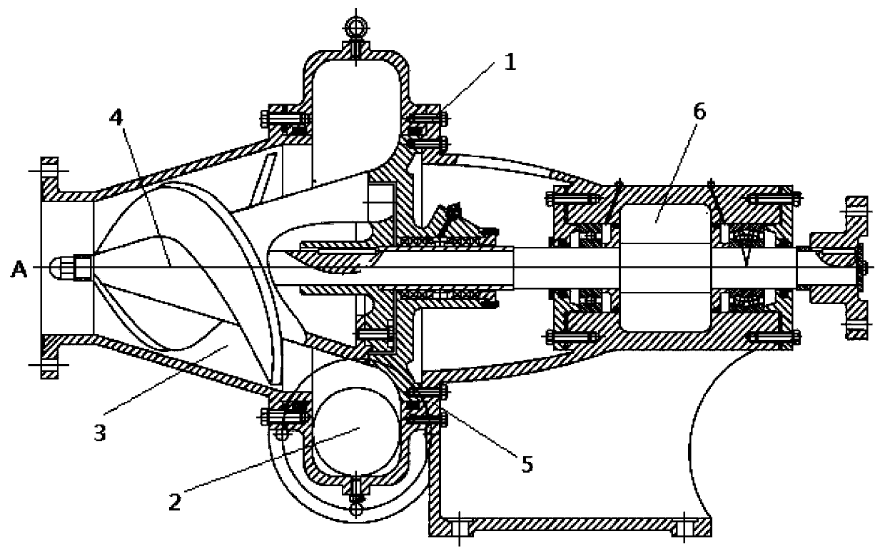
[0016] Connect point A to the water inlet pipe, open the bottom valve ⑸ to fill the pressurized water chamber ⑶ with water, adjust the regulating valve ⑴ to the desired value, turn on the motor ⑹, and the motor shaft drives the spiral impeller ⑷ to perform high-speed rotation, forcing the pressurized water chamber The liquid in the water chamber ⑶ rotates, and the liquid is discharged from the discharge short pipe ⑵ by centrifugal action, and the water is sucked into the pressurized water chamber ⑶ from A, and the cycle is like this.


PUM


Abstract

Disclosed is a spiral gravel pump device. The spiral gravel pump device mainly comprises an adjusting valve, a discharging short pipe, a water pumping chamber, an impeller, a bottom valve and a motor. The spiral impeller drives fluid to rotate and discharges the fluid out of the discharging short pipe under the action of centrifugal force. The spiral gravel pump device is characterized in that the bottom valve injects water into the water pumping chamber, when the adjusting valve is adjusted to a desired value, the motor drives the spiral impeller to rotate, by means of the centrifugal effect of the spiral impeller, fluid is discharged from the discharging short pipe and further the water can be sucked into the water pumping chamber from A. The spiral gravel pump device works as the following steps of opening the bottom valve (5) to filling the water pumping chamber (3) with water, adjusting the adjusting valve (1) to control water outflow, starting the motor (6) to drive the spiral impeller (4) to rotate and discharging fluid from the discharging short pipe (2) to suck the water into the water pumping chamber (3) from A.

Description

technical field [0001] The invention is a spiral gravel pump equipment, specifically, it is applied to the transmission equipment of large particles of impurities. Background technique [0002] Although the existing various impurity pumps have good performance in pumping mixed liquid containing impurities and particles, due to the limitation of the structure of the pump body, winding and clogging failures often occur during operation, which seriously damages the materials, and cannot be used to pump long fibers, Large particle size solids and non-damaging materials are far from meeting the needs of many industries. Contents of the invention [0003] The object of the present invention is to provide a screw type centrifugal pump device without clogging, winding and little damage. [0004] The purpose of the present invention is achieved like this: [0005] It mainly includes regulating valve ⑴, short discharge pipe ⑵, pressurized water chamber ⑶, spiral impeller ⑷, bottom...

Claims


Application Information

Patent Timeline
Patent Type & Authority Applications(China)
IPC IPC(8): F04D1/04
Inventor 王瑛李忠喜
Owner 南京恒誉名翔科技有限公司
Learn More