
Hydraulic buffering device using shape memory alloy

A memory alloy and hydraulic buffer technology, applied in liquid shock absorbers and other directions, can solve the problems of low utilization rate, difficult engineering practice, small buffer stroke, etc., and achieve the effect of high material utilization rate, simple stress state, and improved displacement.

Inactive Publication Date: 2014-06-18
UNIV OF SCI & TECH OF CHINA
View PDF8 Cites 7 Cited by
  • Summary
  • Abstract
  • Description
  • Claims
  • Application Information

AI Technical Summary

Problems solved by technology

According to this characteristic, a variety of devices using shape memory alloys for buffering and energy consumption have emerged, mainly using the stretching mechanism of alloy wires. However, these devices generally have a small buffer stroke and are difficult to apply to engineering practice
There are also some designs that try to use the bending deformation mechanism of memory alloy components such as alloy beams and alloy shells to buffer energy consumption. Although a relatively large stroke can be obtained, the material is only fully phase-transformed locally, and the utilization rate is low.

Method used


Image

  • Hydraulic buffering device using shape memory alloy
  • Hydraulic buffering device using shape memory alloy
  • Hydraulic buffering device using shape memory alloy

Examples


Embodiment Construction

[0020] The specific implementation manners of the present invention will be described in detail below in conjunction with the technical solutions and with reference to the accompanying drawings.

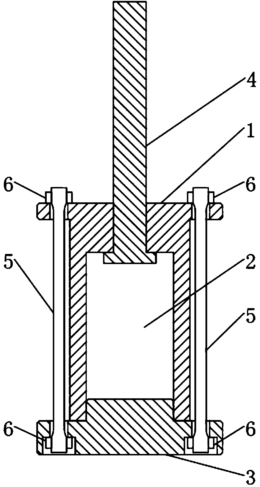
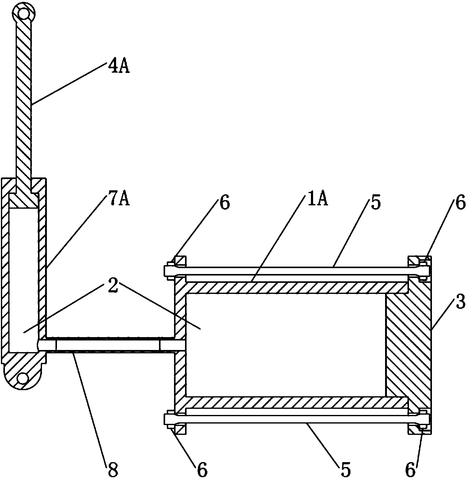
[0021] A basic model embodiment of the present invention, a hydraulic buffer device using shape memory alloy, such as figure 1 As shown, it includes hydraulic cylinder block 1, hydraulic oil 2, large piston 3, small plunger 4, shape memory alloy pull rod 5, fastening nut 6 and other components.

[0022] There is a sealing hole with a small area in the center of one end of the hydraulic cylinder 1, which is matched with the small plunger 4, and there are mounting holes symmetrically distributed around this end, and a sealing hole with a larger area at the other end, which is matched with the large piston 3. The area ratio of the large piston to the small plunger, that is, the area ratio of the large sealing hole to the small sealing hole is about 5 to 15 times. The edge of one end of...


PUM


Abstract

Provided is a hydraulic buffering device using shape memory alloy. Power consumption and reset are carried out through single-shaft stretching of a pseudo-elastic shape memory alloy pull rod. The function of amplifying displacement is achieved through the area ratio of a large piston and a small piston in a hydraulic device. When the shape memory alloy pull rod deforms a little, namely the large piston moves a little relative to a hydraulic cylinder, a small plunger connected with the outside moves a long distance relative to the hydraulic cylinder, and the function of buffering impact of the outside is achieved. On one hand, the buffering stroke is large; on the other hand, the shape memory alloy pull rod is simple and uniform in stress state, high in phase change utilization rate and large in energy consumption. Action force during buffering is stable, and the buffering device can be reset timely, repeatedly used continuously and suitable for buffering protection of important military and civil devices.

Description

technical field [0001] The invention relates to a buffer device, in particular to a hydraulic buffer device utilizing a shape memory alloy for energy dissipation and reset. Background technique [0002] Buffer devices are widely used in machinery, vehicles and earthquake-resistant buildings. The simplest buffer device is a spring, but usually its damping coefficient is low, it cannot quickly attenuate shocks, and it is easy to cause multiple impacts and other problems, so it needs to be used in combination with other damping components. According to the relationship between the buffer and the speed and displacement, it can be roughly divided into speed type, displacement type and hybrid type buffer. Speed-type shock absorbers, such as common hydraulic shock absorbers, have a large difference in force at different impact speeds. When the speed exceeds a certain speed limit, the buffer force will be too large. A device that utilizes the principles of metal elastic-plastic de...

Claims


Application Information

Patent Timeline
IPC IPC(8): F16F9/19F16F9/22
Inventor 张科唐志平
Owner UNIV OF SCI & TECH OF CHINA
Learn More