SV network sampling-based double-circuit line single-phase earth fault distance measurement method

A single-phase ground fault, double-circuit line technology, applied in the direction of measuring electricity, measuring devices, fault locations, etc., can solve the problems of mutual inductance influence on ranging accuracy, zero-sequence compensation coefficient influence, failure to provide fault location information, etc.

Active Publication Date: 2014-06-18
STATE GRID PUTIAN ELECTRIC POWER SUPPLY +2
View PDF5 Cites 21 Cited by
  • Summary
  • Abstract
  • Description
  • Claims
  • Application Information

AI Technical Summary

Problems solved by technology

The traveling wave method utilizes the transmission properties of fault transient traveling waves for distance measurement. It has high precision and is not affected by the operation mode and excessive resistance. application
The impedance method uses the voltage and current after the fault to calculate the impedance of the fault loop, and performs distance measurement according to the characteristic that the length of the line is proportional to the impedance. When measuring terminal faults, the distance measurement accuracy is seriously affected by the transition resistance of the fault point and the zero-sequence mutual inductance between lines.
There is zero-sequence mutual inductance between double-circuit lines on th

Method used


Image

  • SV network sampling-based double-circuit line single-phase earth fault distance measurement method
  • SV network sampling-based double-circuit line single-phase earth fault distance measurement method
  • SV network sampling-based double-circuit line single-phase earth fault distance measurement method

Examples


Embodiment Construction

[0015] The technical solution of the present invention will be further described in detail according to the accompanying drawings.

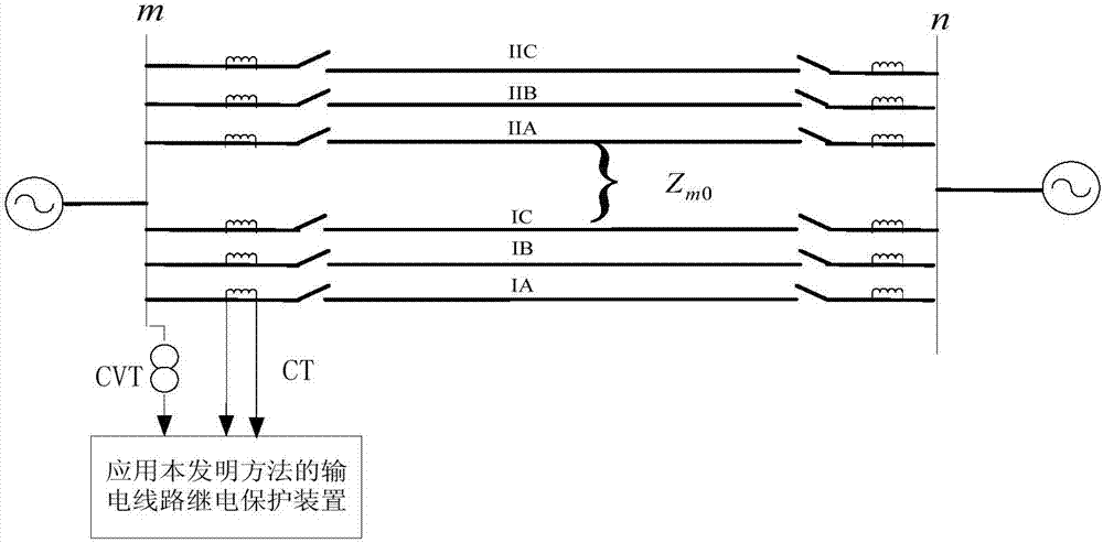
[0016] figure 1 It is a schematic diagram of a double-circuit power transmission system on the same pole applying the present invention. figure 1 CVT is a voltage transformer, and CT is a current transformer. In the smart substation, the SV network communication network is carried out on the sampling digital signal transmission channel. After the merging unit collects the AC analog output of the voltage transformer CVT and the current transformer CT in real time, the merging unit collects the collected voltage transformer CVT and current transformer. The AC analog output of the CT is converted into a sampled digital signal, which is directly transmitted to the relay protection device through optical fiber communication.

[0017] A kind of double-circuit line single-phase grounding fault distance measurement method based on SV network sampling o...


PUM


Abstract

The invention discloses an SV network sampling-based double-circuit line single-phase earth fault distance measurement method which is used for measuring the fault phase voltage mutational volume, the fault phase current mutational volume, the zero-sequence current and the other two normal phase voltages of an I-circuit line at the protection mounting position of a double-circuit line on the same pole, and measuring the zero-sequence current of a II-circuit line; calculating the fault phase voltage when the I-circuit line operates normally, sequentially calculating the positioning vector function of each point on the I-circuit line of the double-circuit line on the same pole until the full length of the I-circuit line of the double-circuit line on the same pole, and selecting the distance between the point with the smallest positioning vector function value on the I-circuit line of the double-circuit line on the same pole and the protection mounting position of the double-circuit line on the same pole as the fault distance. According to the method, the voltage of the circuit before the fault does not need to be remembered, and a voltage protection loop of the circuit before the fault does not need to be set; the influence of the zero-sequence mutual inductive impedance among the lines, the transition resistance and the load current on the precision of measurement of the fault distance is eliminated, and no fault distance measurement dead zone exists in protecting the single phase grounding fault of the outlet single-circuit line.

Description

technical field [0001] The invention relates to the technical field of electric power system relay protection, in particular to a method for measuring the single-phase grounding fault distance of a double-circuit line based on SV network sampling. Background technique [0002] Divided from the electrical quantity used for distance measurement, fault location methods can be divided into two categories: double-ended ranging and single-ended ranging. The double-terminal fault location method is a method to determine the fault location of the transmission line by using the electrical quantity at both ends of the transmission line. It needs to obtain the electrical quantity of the opposite end through the channel, so it is highly dependent on the channel, and it is also vulnerable to the double-terminal sampling value in actual use. Synchronization effects. The single-ended ranging method is a method that only uses the voltage and current data at one end of the transmission line...

Claims


Application Information

Patent Timeline
IPC IPC(8): G01R31/08G01R31/02
Inventor 林富洪曾惠敏陈文景徐致远李振华
Owner STATE GRID PUTIAN ELECTRIC POWER SUPPLY
Why Eureka
Try Eureka