A Coherent Wind Lidar Pulse Signal Transmitting System

A laser radar and laser signal technology, applied in radio wave measurement systems, measurement devices, and use of re-radiation, etc., can solve the problems of single adjustment method and high requirements for lasers, improve transmission quality, wide modulation range, and avoid polarization state. changing effect

Active Publication Date: 2016-06-01
BEIJING RES INST OF SPATIAL MECHANICAL & ELECTRICAL TECH
View PDF3 Cites 0 Cited by
  • Summary
  • Abstract
  • Description
  • Claims
  • Application Information

AI Technical Summary

Problems solved by technology

The main source that affects the coherence of the laser emission signal is the laser emission system. The current laser emission pulse method is to place an electro-optic or acousto-optic Q-switched switch in the laser resonator. Although this method can achieve single-frequency laser output, the adjustment method Single, relatively high requirements for lasers

Method used


Image

  • A Coherent Wind Lidar Pulse Signal Transmitting System
  • A Coherent Wind Lidar Pulse Signal Transmitting System
  • A Coherent Wind Lidar Pulse Signal Transmitting System

Examples


Embodiment approach 1

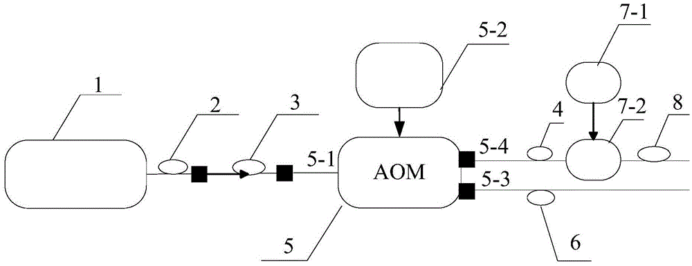
[0027] Embodiment 1: This embodiment is as follows figure 1 As shown, the fiber laser 1 emits a 2 μm continuous laser signal, and outputs it through the first single-mode polarization-maintaining fiber 2, and the 2 μm laser signal enters the fiber-optic online polarizer 3 to generate linearly polarized laser light, and then passes the 2 μm acousto-optic frequency shift The input port 5-1 of the device 5 enters the 2 μm acousto-optic frequency shifter 5;

[0028] Adjust the voltage of the frequency modulation port 5-2 to 5.2V to achieve the maximum diffraction efficiency, and output two laser signals;

[0029] The laser beam output by the first-order diffraction port 5-4 is output through the second single-mode polarization-maintaining optical fiber 4, enters the chopper 7-2 through the input port of the chopper 7-2, and the external drive signal passes through the external drive signal interface 7- 1 into the chopper 7-2, by adjusting the period and duty ratio of the external...

Embodiment approach 2

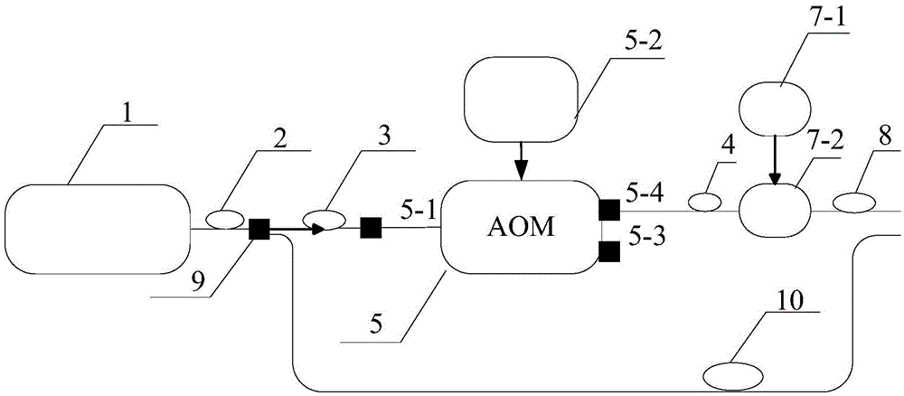
[0030] Implementation mode two: this implementation mode is as follows figure 2 As shown, the fiber laser 1 emits a 2 μm continuous laser signal, and outputs it through the first single-mode polarization-maintaining fiber 2, and divides it into the first laser branch signal and the second laser branch signal through the fiber beam splitter 9, and the first laser branch signal The signal enters the optical fiber online polarizer 3 to generate linearly polarized laser light, and then enters the 2 μm acousto-optic frequency shifter 5 through the input port 5-1 of the 2 μm acousto-optic frequency shifter 5;

[0031] Adjust the voltage of the frequency modulation port 5-2 to 5.2V to achieve the maximum diffraction efficiency, and output two laser signals;

[0032] The laser beam output by the first-order diffraction port 5-4 is output through the second single-mode polarization-maintaining optical fiber 4, enters the chopper 7-2 through the input port of the chopper 7-2, and the e...

Embodiment approach 3

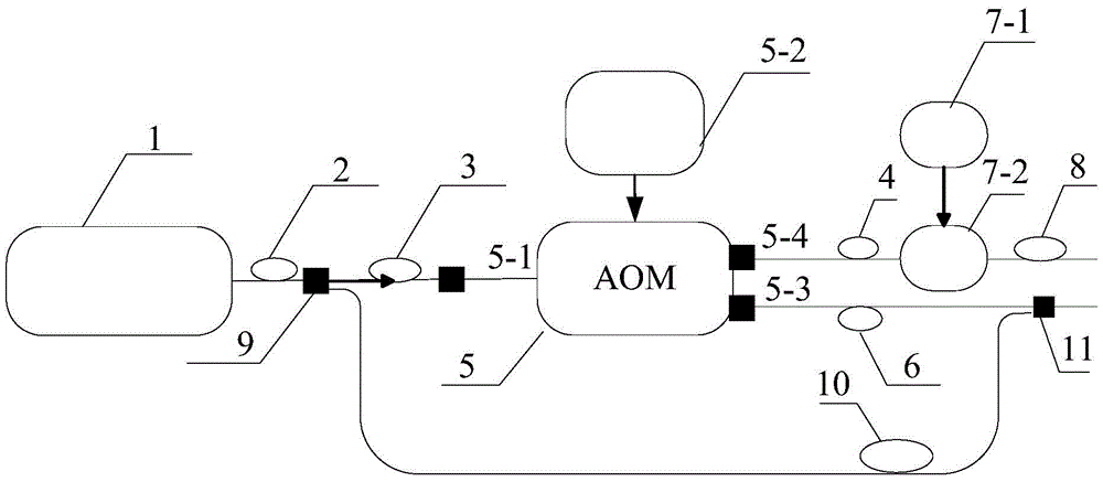
[0034] Implementation Mode Three: This implementation mode is as follows image 3 As shown, the fiber laser 1 emits a 2 μm continuous laser signal, and outputs it through the first single-mode polarization-maintaining fiber 2, and divides it into the first laser branch signal and the second laser branch signal through the fiber beam splitter 9, and the first laser branch signal The signal enters the optical fiber online polarizer 3 to generate linearly polarized laser light, and then enters the 2 μm acousto-optic frequency shifter 5 through the input port 5-1 of the 2 μm acousto-optic frequency shifter 5;

[0035] Adjust the voltage of the frequency modulation port 5-2 to 5.2V to achieve the maximum diffraction efficiency, and output two laser signals;

[0036] The laser beam output by the first-order diffraction port 5-4 is output through the second single-mode polarization-maintaining optical fiber 4, enters the chopper 7-2 through the input port of the chopper 7-2, and the ...


PUM


Abstract

A coherent anemometry laser radar pulse signal transmitting system comprises a fiber laser, a first single-mode polarization maintaining optical fiber, an optical fiber online type polarizer, a second single-mode polarization maintaining optical fiber, a two-micron acousto-optic frequency shifter, a third single-mode polarization maintaining optical fiber, a chopper and a fourth single-mode polarization maintaining optical fiber. Laser signals pass through a two-micron optical fiber laser, the first single-mode polarization maintaining optical fiber, the optical fiber online type polarizer and the two-micron acousto-optic frequency shifter in sequence to generate two channels of laser signals, one channel of laser signals pass through the chopper and the fourth single-mode polarization maintaining optical fiber to form coherent anemometry laser radar pulse signals, and the other channel of laser signals pass through the third single-mode polarization maintaining optical fiber to form coherent anemometry laser radar reference local oscillator laser signals. The coherent anemometry laser radar pulse signal transmitting system can supply laser transmitting signals which are stable and adjustable in frequency and adjustable in pulse repeating frequency and pulse width for two-micron all-fiber coherent laser anemometry radar systems, and is simple in structure, stable in performance and easy to achieve in engineering.

Description

technical field [0001] The invention relates to a coherent wind laser radar pulse signal transmitting system, which can provide laser transmitting signals with stable frequency, adjustable pulse repetition frequency and pulse width for the 2μm all-fiber coherent laser wind radar system, and is mainly used in 2μm All-fiber coherent wind lidar system. Background technique [0002] Coherent laser wind radar is the preferred laser remote sensing instrument for global high-precision and high-resolution atmospheric wind field measurement. It is widely used in extreme weather measurement fields such as low-altitude atmospheric wind field, turbulence, cyclone, and local thunderstorms. [0003] The all-fiber 2μm laser emission system is more and more popular in the world due to its compact structure, mature laser technology, eye-safe laser band, and being in the atmospheric window. Laser emission is a key component of a coherent lidar wind radar system, and its performance character...

Claims


Application Information

Patent Timeline
Patent Type & Authority Patents(China)
IPC IPC(8): G01S7/484G01S13/95
CPCG01S7/484G01S17/95Y02A90/10
Inventor 高龙王遨游荣微孙琼阁
Owner BEIJING RES INST OF SPATIAL MECHANICAL & ELECTRICAL TECH
Why Eureka
Try Eureka