Construction Method of Velocity Error Function of Bistatic Forward-Looking Synthetic Aperture Radar Moving Target

A construction method and speed error technology, applied in the field of radar, can solve problems such as no relevant public documents

Active Publication Date: 2016-02-17
UNIV OF ELECTRONICS SCI & TECH OF CHINA
View PDF4 Cites 0 Cited by
  • Summary
  • Abstract
  • Description
  • Claims
  • Application Information

AI Technical Summary

Problems solved by technology

[0006] In the literature: "Synthetic capture imaging radar and moving targets", R.K. Raney, IEEE Trans. on Aerospace and Electronic Systems, vol. no.3, pp.1185–1191, 1996, and literature: "Moving target relative speed estimation and refocusing insynthetic capture radar images", T.K.Sjogren, V.T.Vu, M.I.Pettersson, A.Gustavsson, and L.M.H.Ulander, IEEETrans.onGeoscienceandRemoteSenspping.10, vol.48, no. In .3799-3815, 2010, the most commonly used and most effective self-focusing algorithm for moving target imaging was studied. However, when the speed of the moving target is unknown, the self-focusing algorithm involves the selection of the optimal step size, and the bistatic Issues such as the impact of moving target motion on imaging in forward-looking SAR have not yet been researched in relevant open literature

Method used


Image

  • Construction Method of Velocity Error Function of Bistatic Forward-Looking Synthetic Aperture Radar Moving Target
  • Construction Method of Velocity Error Function of Bistatic Forward-Looking Synthetic Aperture Radar Moving Target
  • Construction Method of Velocity Error Function of Bistatic Forward-Looking Synthetic Aperture Radar Moving Target

Examples


Embodiment Construction

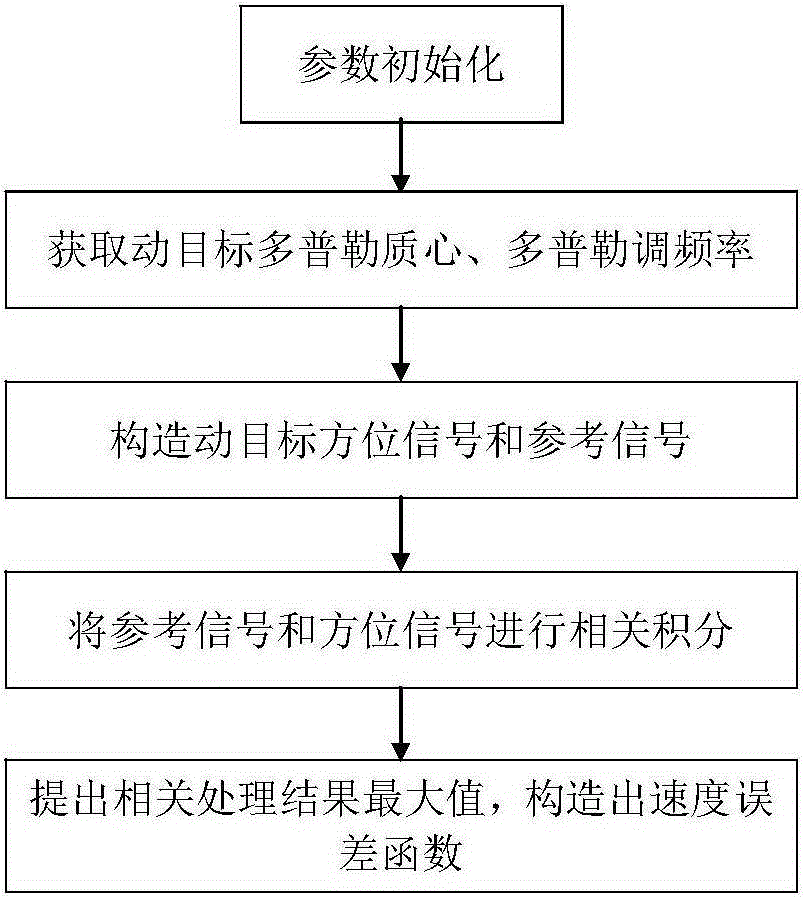
[0053] The present invention mainly adopts the method of simulation experiment to verify, and all steps and conclusions are verified correctly on Matlab2012. The present invention will be further described in detail below in conjunction with the accompanying drawings and specific embodiments. The schematic diagram of the process is as follows figure 1 As shown, the specific process is as follows:

[0054] Step 1: System parameter initialization

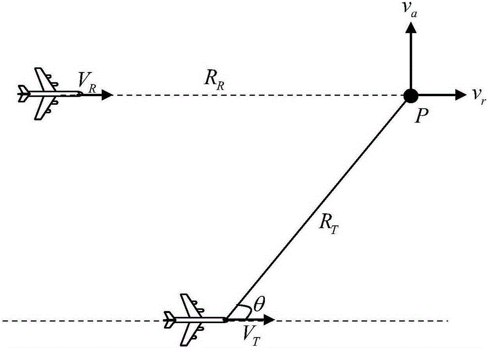
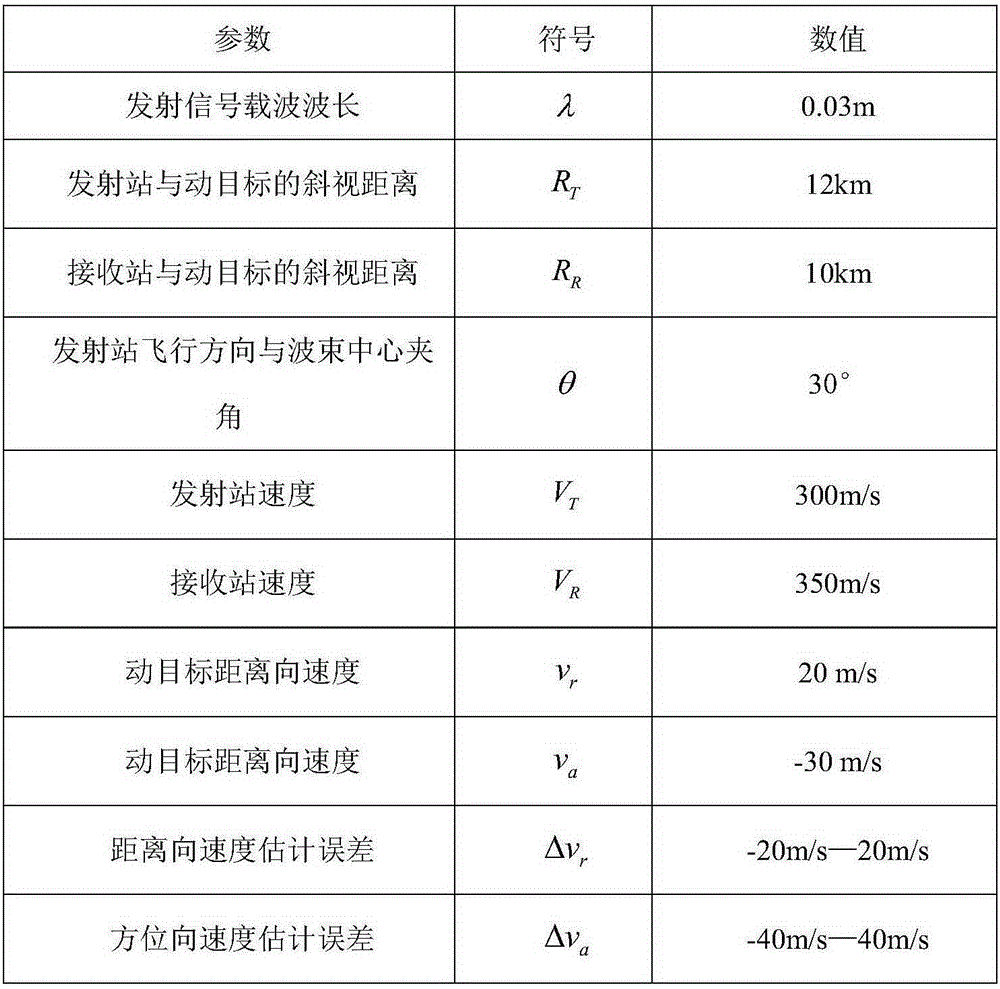
[0055] The geometric structure diagram of the bibase forward-looking SAR adopted in the specific embodiment of the present invention is as follows figure 2 As shown, the system parameter table adopted is as follows image 3 As shown, among them, the moving target P distance to the moving speed v r is 20m / s, the azimuth movement speed v a is -30m / s, the squint distance R between the transmitting station and the moving target P T is 12km, the speed of the launching station is V T is 300m / s, the angle θ between the flight directi...


PUM


Abstract

The invention discloses a method for constructing a velocity error function of a bistatic forward-looking synthetic aperture radar moving target. The method of the invention first deduces the Doppler centroid and Doppler modulation frequency of the moving target in the bistatic forward-looking SAR mode and constructs a moving target. The target azimuth signal is then correlated with the moving target azimuth signal by using the reference function with velocity estimation error, and finally the maximum value of the correlation integral results under different moving target velocity estimation errors is extracted to construct the velocity error function. The speed error function not only conducts quantitative analysis and research on the influence of moving target motion on imaging, but also can be used to complete bistatic forward-looking SAR moving target motion compensation, determine the optimal step size selection of azimuth self-focusing, etc., so as to achieve high efficiency , Realize the focused imaging of bistatic forward-looking SAR moving targets with high precision.

Description

technical field [0001] The invention belongs to the technical field of radar, and in particular relates to the moving target imaging of the bistatic forward-looking SAR in the synthetic aperture radar (Synthetic Aperture Radar, SAR) imaging technology. Background technique [0002] Synthetic aperture radar is an all-weather, all-weather modern high-resolution microwave remote sensing imaging radar, which uses the relative motion between the radar antenna and the target area to obtain high spatial resolution. In the fields of terrain mapping, vegetation analysis, ocean and hydrological observation, environment and disaster monitoring, and resource exploration, SAR has played an increasingly important role. However, due to the limitation of its own working system, the existing single-base SAR cannot realize high-resolution imaging of the forward-looking area of ​​the aircraft, so that the SAR technology cannot fully play its role in the forward-looking aircraft to the ground, ...

Claims


Application Information

Patent Timeline
Patent Type & Authority Patents(China)
IPC IPC(8): G01S13/90
CPCG01S13/904G01S13/9043
Inventor 李中余武俊杰孙稚超杨海光黄钰林杨建宇
Owner UNIV OF ELECTRONICS SCI & TECH OF CHINA
Why Eureka
Try Eureka