Optical Processor of Synthetic Aperture LiDAR Based on Bandpass Filter

A synthetic aperture laser and imaging radar technology, applied in the field of optical processors, can solve the problems of complex imaging process, no involvement, small optical imaging results, etc.

Active Publication Date: 2017-05-24
SHANGHAI INST OF OPTICS & FINE MECHANICS CHINESE ACAD OF SCI
View PDF4 Cites 0 Cited by
  • Summary
  • Abstract
  • Description
  • Claims
  • Application Information

AI Technical Summary

Problems solved by technology

For the intensity-type synthetic aperture lidar imaging radar echo signal, there are three parts in the range spectrum plane after the range Fourier transform, positive frequency, negative frequency and zero frequency, but the azimuth phase quadratic term matched filtering process can be Only the negative frequency part can achieve azimuth focusing. In addition, the zero-frequency light intensity is much stronger than the negative-frequency light intensity. Therefore, the positive frequency and zero-frequency parts that cannot be focused will seriously affect the observation of imaging results. However, this invention The patent does not involve the filtering of positive frequency and zero frequency parts
In addition, because the optical imaging result in this invention patent is small, the imaging result can only be received by the CCD and then displayed by the computer, and the imaging process is more complicated

Method used


Image

  • Optical Processor of Synthetic Aperture LiDAR Based on Bandpass Filter
  • Optical Processor of Synthetic Aperture LiDAR Based on Bandpass Filter
  • Optical Processor of Synthetic Aperture LiDAR Based on Bandpass Filter

Examples


Embodiment Construction

[0015] The present invention will be described in further detail below in conjunction with the accompanying drawings and embodiments, but the protection scope of the present invention should not be limited thereby.

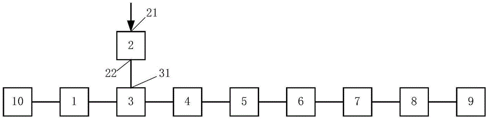
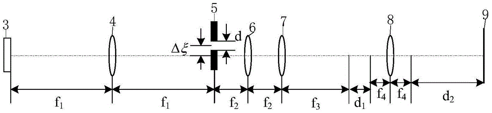
[0016] see first figure 1 , figure 1 It is a structural schematic diagram of the optical processor of the band-pass filter-based synthetic aperture laser imaging radar of the present invention. As can be seen from the figure, the present invention is based on the optical processor of the synthetic aperture laser imaging radar with bandpass filtering, and its composition includes a laser 10, a collimating beam expander unit 1, a synthetic aperture laser imaging radar data receiving unit 2, and a transmissive intensity type liquid crystal space A light modulator 3, a first spherical lens 4, a slit 5, a second spherical lens 6, a cylindrical lens 7, a third spherical lens 8, and a light screen 9, sequentially along the direction of the optical axis of the laser ligh...


PUM


Abstract

A synthetic aperture laser imaging radar optical processor based on band-pass filter conducts imaging process on target echoed data of a synthetic aperture laser imaging radar through an optical imaging processing method. The synthetic aperture laser imaging radar optical processor based on the band-pass filter comprises an optical master, a collimation beam expanding unit, a synthetic aperture laser imaging radar echoed data storage unit, a transmission-type and intensity-type liquid crystal spatial light modulator, a first spherical lens, a slit, a second spherical lens, a cylindrical lens, a third spherical lens and an optical screen. According to the rationale, the target echoed data received by the synthetic aperture laser imaging radar echoed data storage unit is loaded onto the intensity-type liquid crystal spatial light modulator and conducts modulation on incident planar optical waves; after emergent optical waves pass through the band-pass filter, the focusing of the range direction and the azimuth direction can be achieved simultaneously, and an imaging result is amplified and displayed on the optical screen. By means of the synthetic aperture laser imaging radar optical processor based on the band-pass filter, the band-pass filter of a synthetic aperture imaging laser radar intensity-type echoed signal is achieved, the imaging result is easy to observe, and the synthetic aperture laser imaging radar optical processor based on the band-pass filter has an extensive application prospect in the future airborne and satellite borne synthetic aperture laser imaging radar systems.

Description

technical field [0001] The invention relates to a synthetic aperture laser imaging radar, in particular to an optical processor of a synthetic aperture laser imaging radar based on band-pass filtering, which uses a filter to complete band-pass filtering, and then realizes radar echo signal focusing in the range direction and azimuth direction at the same time, Imaging results are displayed on the light screen. Background technique [0002] The principle of Synthetic Aperture Lidar Imaging Lidar (SAIL) is derived from the principle of Synthetic Aperture Radar (SAR) in the radio frequency field. It is the only optical imaging observation method reported abroad that can obtain centimeter-level resolution at long distances. The emission laser of the synthetic aperture laser imaging radar adopts optical frequency linear modulation, that is, chirp modulation, and the optoelectronic heterodyne reception adopts the deskewing demodulation method, that is, the same chirp emission lase...

Claims


Application Information

Patent Timeline
Patent Type & Authority Patents(China)
IPC IPC(8): G01S17/89
CPCG01S17/90
Inventor 孙建锋孙志伟周煜张宁蔡光宇李光远张国刘立人
Owner SHANGHAI INST OF OPTICS & FINE MECHANICS CHINESE ACAD OF SCI
Why Eureka
Try Eureka