
Liquid crystal display device and manufacturing method thereof

A liquid crystal display device and liquid crystal display technology, which are applied in nonlinear optics, instruments, optics, etc., can solve the problems of reduced transmittance and prolonged response time of liquid crystal display devices, and achieve short response time, weakened inhibition, and high The effect of penetration

Active Publication Date: 2014-06-18
KUSN INFOVISION OPTOELECTRONICS
View PDF3 Cites 13 Cited by
  • Summary
  • Abstract
  • Description
  • Claims
  • Application Information

AI Technical Summary

Problems solved by technology

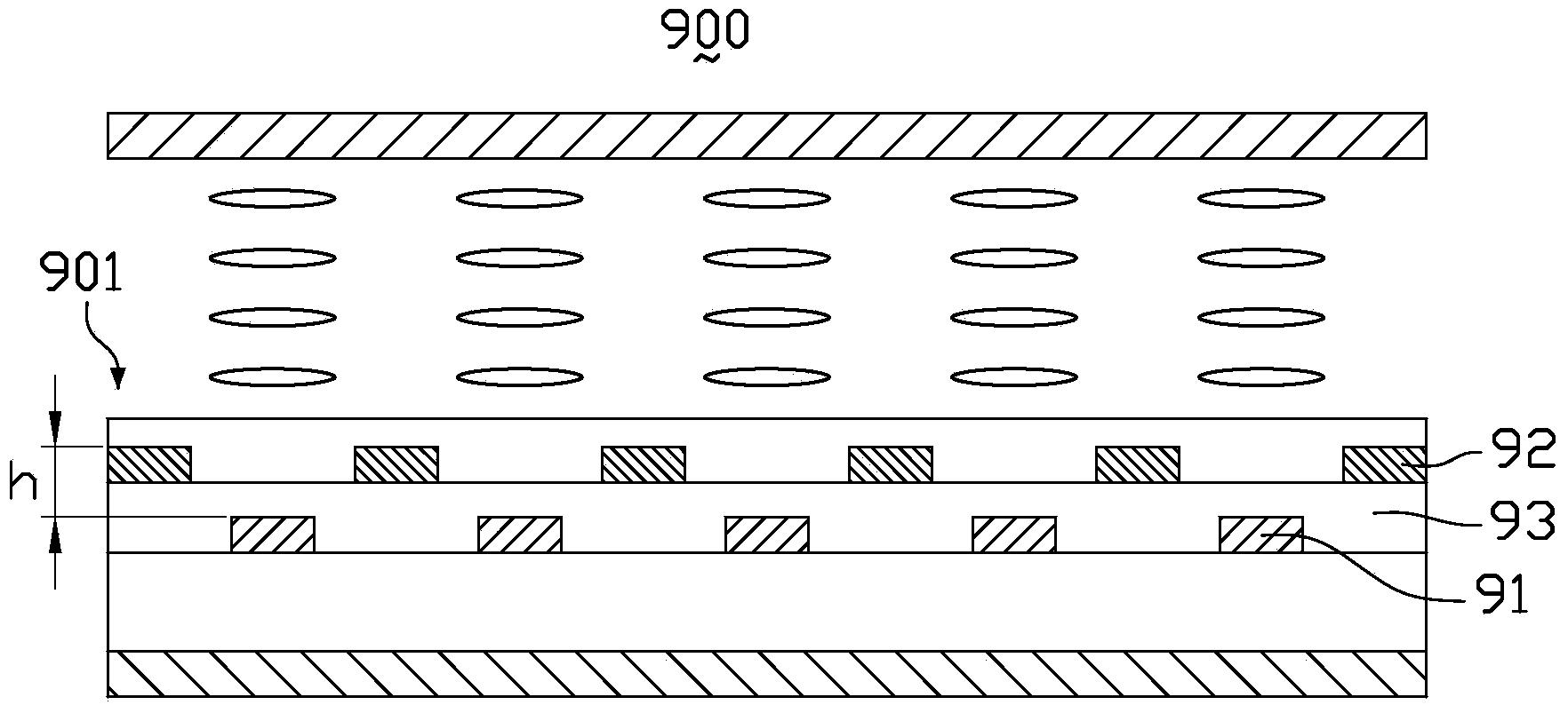
The vertical height difference h causes a vertical electric field to exist between the first electrode 91 and the second electrode 92, and this vertical electric field has a certain inhibitory effect on the rotation of the liquid crystal molecules in the plane, so that the transmittance of the liquid crystal display device is reduced and the response time is shortened. long

Method used


Image

  • Liquid crystal display device and manufacturing method thereof
  • Liquid crystal display device and manufacturing method thereof
  • Liquid crystal display device and manufacturing method thereof

Examples


Embodiment Construction

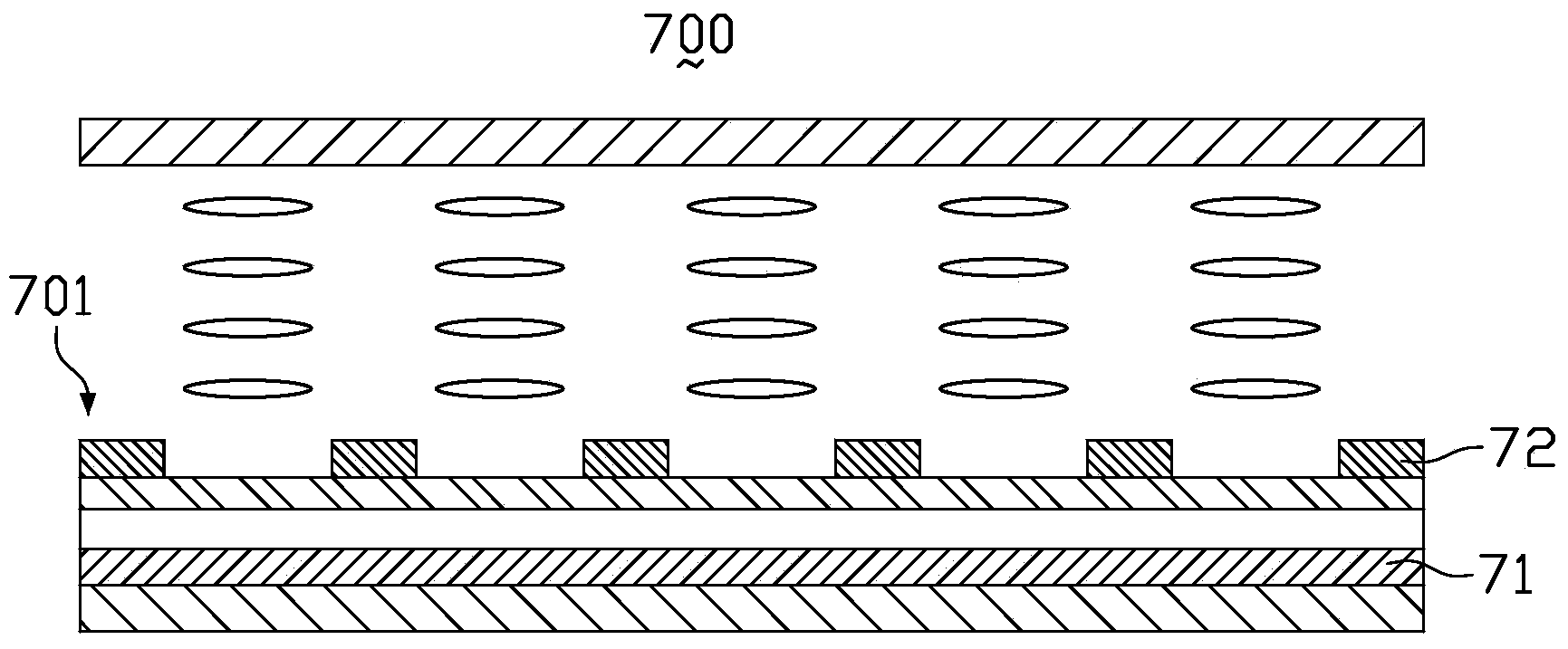
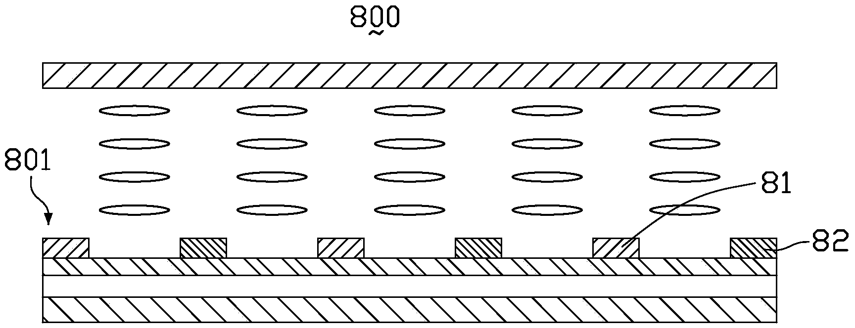
[0040] In order to further explain the technical means and effects of the present invention to achieve the intended purpose of the invention, the specific implementation, structure, and characteristics of the liquid crystal display device and its manufacturing method proposed according to the present invention will be described below in conjunction with the accompanying drawings and preferred embodiments. and its effects are described in detail as follows:

[0041] The aforementioned and other technical contents, features and effects of the present invention will be clearly presented in the following detailed description of preferred embodiments with reference to the drawings. Through the description of specific embodiments, the technical means and effects of the present invention to achieve the intended purpose can be understood more deeply and specifically, but the attached drawings are only for reference and description, and are not used to explain the present invention lim...


PUM


Abstract

A liquid crystal display device comprises a first base plate, a liquid crystal display layer and a second base plate. The first base plate comprises a first transparent substrate, a first insulating layer, a first electrode, a second insulating layer and a second electrode, wherein the first insulating layer, the first electrode, the second insulating layer and the second electrode are sequentially formed on the first transparent substrate. Part of the first insulating layer is covered with the first electrode; the second insulating layer is arranged on the first electrode and the first insulating layer; the second insulating layer is provided with a plurality of second concave parts which are concaved towards the first insulating layer; the second concave parts correspond to the portions, which are not covered with the first electrode, of the surface of the second insulating layer; part of the second electrode is arranged on the surface of the second insulating layer and located in the second concave parts. The liquid crystal display device has a high penetration rate and a short response time.

Description

technical field [0001] The invention relates to the technical field of liquid crystal display, in particular to a liquid crystal display device and a manufacturing method thereof. Background technique [0002] Thin Film Transistor-Liquid Crystal Display (TFT-LCD) is widely used in the field of flat panel display due to its low radiation, thin thickness and low power consumption. Initially, most TFT-LCDs were in Twisted Nematic (TN) mode. However, the first electrode and the second electrode of the TN type liquid crystal display are formed on the upper and lower substrates respectively, and the liquid crystal molecules are Rotating in a plane perpendicular to the substrate, due to the optical anisotropy of the liquid crystal molecules, the optical path of light entering the human eye after passing through the liquid crystal molecules from different angles is different, so the display effect is different, resulting in a relatively small viewing angle range. [0003] In order ...

Claims


Application Information

Patent Timeline
IPC IPC(8): G02F1/1343G02F1/1333
Inventor 钟德镇戴文君潘新叶
Owner KUSN INFOVISION OPTOELECTRONICS
Learn More