An experimental device for dynamic demonstration of cutting tool working angle changes

A technology of working angle and cutting processing, which is applied in the field of experimental teaching aids, can solve the problems of irrational effect, not intuitive enough, and poor help in learning and understanding the working angle of cutting tools, and achieve the effect of simple structure, easy operation and strong help

Inactive Publication Date: 2016-01-20
NORTHEASTERN UNIV LIAONING
View PDF4 Cites 0 Cited by
  • Summary
  • Abstract
  • Description
  • Claims
  • Application Information

AI Technical Summary

Problems solved by technology

[0002] The tool angle is an important parameter used to describe the surface space position of the cutting part of the tool. It is also an important parameter for studying the cutting performance of the cutting tool and the change law of the tool angle. The tool angle can be divided into the tool label angle and the tool working angle. The tool working angle The angle is the actual cutting angle of the cutting tool in the working state, and the working angle of the cutting tool is in a dynamic change under the working state, but this dynamic change is difficult to observe with the naked eye. At this stage, I want to understand the working angle of the cutting tool in depth. The law of dynamic changes can only be learned through graphic descriptions, static teaching aids or animation demonstrations, and these existing methods are not intuitive enough. They are not very helpful for learning and understanding the laws of dynamic changes in tool working angles, and the effect is not good. reason

Method used


Image

  • An experimental device for dynamic demonstration of cutting tool working angle changes
  • An experimental device for dynamic demonstration of cutting tool working angle changes
  • An experimental device for dynamic demonstration of cutting tool working angle changes

Examples


Embodiment Construction

[0021] The present invention will be further described in detail below in conjunction with the accompanying drawings and specific embodiments.

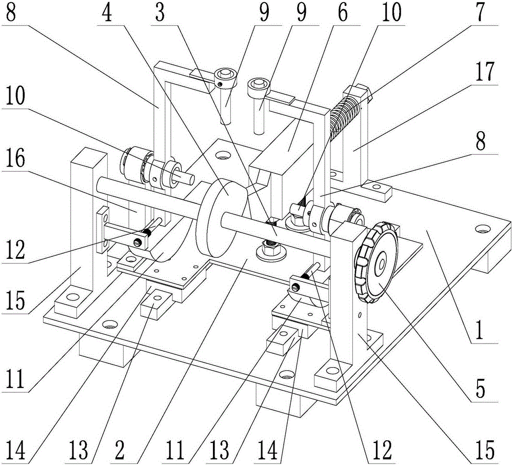
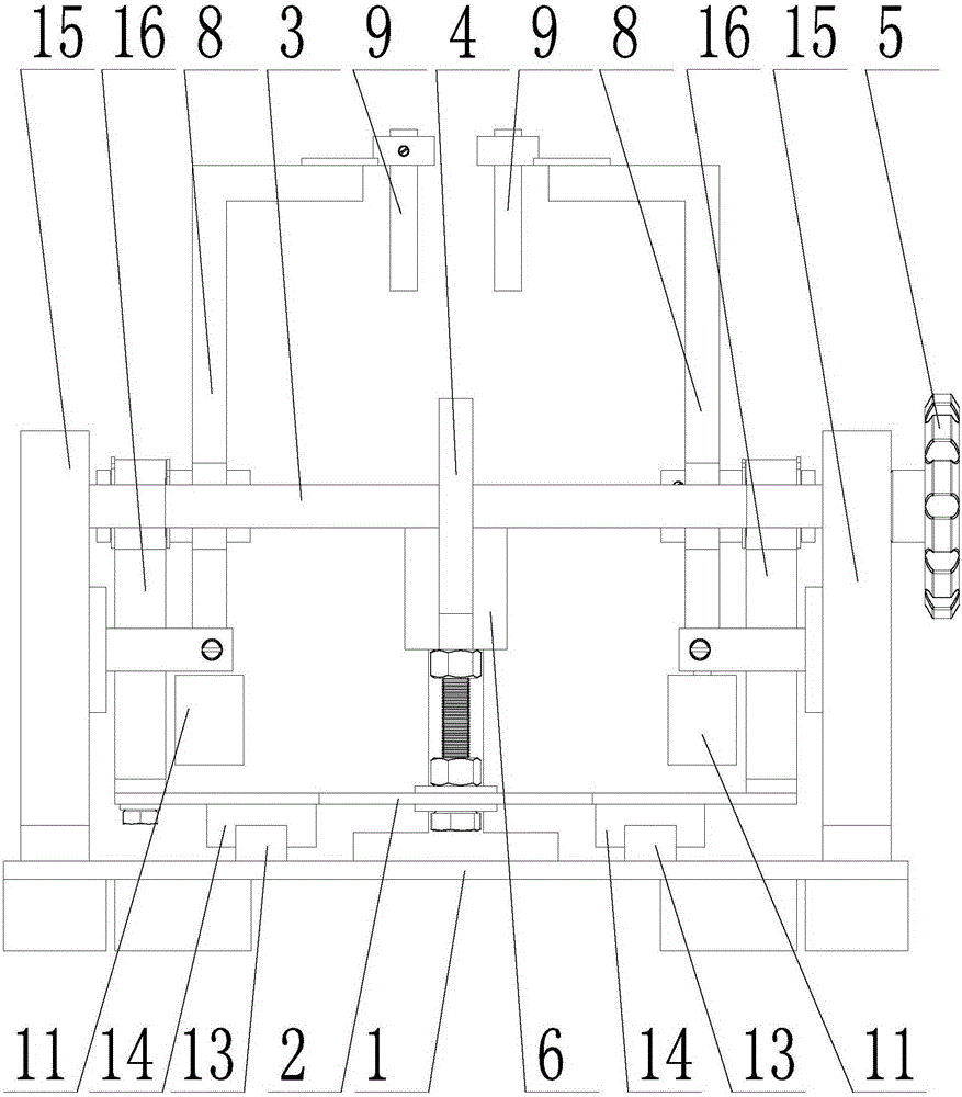
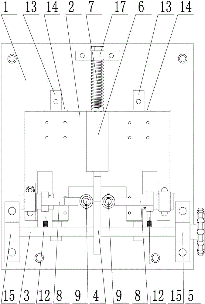
[0022] Such as figure 1 , 2 , 3, and 4, a dynamic demonstration experimental device for cutting tool working angle changes, including a fixed base plate 1, a sliding base plate 2, a rotary shaft 3, a cam 4, a tool 6, a swing frame 8, a vertical light source 9 and a horizontal light source 10. The sliding bottom plate 2 is arranged above the fixed bottom plate 1, and the sliding bottom plate 2 is slidably matched with the fixed bottom plate 1. The tool 6 is fixed on the sliding bottom plate 2, and a spring 7 is connected to the tail end of the tool 6, and the spring 7 passes through The third support 17 is fixed on the fixed base plate 1;

[0023] The rotary shaft 3 is installed on the fixed base plate 1 through the first support 15, the rotary shaft 3 is perpendicular to the feed direction of the tool 6, the cam 4 is fixedly set in ...


PUM


Abstract

The invention discloses a cutting tool working angle variation dynamic demonstration experiment device and belongs to the technical field of experiment training aids. The device is simple in structure, easy and convenient to operate and visual in expression and makes working angle variation rules easy to learn and understand. A sliding bottom plate is arranged above a fixed bottom plate and is in sliding fit with the fixed bottom plate. A tool is fixedly installed on the sliding bottom plate. A spring is connected to the tail end of the tool and fixedly installed on the fixed bottom plate. A rotating shaft is fixedly installed on the fixed bottom plate and is perpendicular to the direction of feed of the tool. A cam is fixedly installed in the middle of the rotating shaft in a sleeved mode and makes contact with the cutting edge of the tool. An oscillation frame is hinged to the sliding bottom plate. Balancing weights are connected to one end of the oscillation frame, vertical light sources are fixedly installed at the other end of the oscillation frame, and horizontal light sources are fixedly installed at the hinging positions of the oscillation frame. The cutting edge of the tool is located in the oscillation centre line of the oscillation frame. Ejector rods of the fixed bottom plate make contact with the oscillation frame. A sector light curtain generated by the vertical light sources is orthogonal to a sector light curtain generated by the horizontal light sources, and the orthogonal of the two sector light curtains coincides with the oscillation centre line of the oscillation frame. The outer contour line of the cam is composed of an Achimedean spiral and an arc.

Description

technical field [0001] The invention belongs to the technical field of experimental teaching aids, and in particular relates to a dynamic demonstration experiment device for the change of the working angle of a cutting tool, which is specifically used for dynamically demonstrating and explaining the law of changing the working angle of the cutting tool during the actual machining process. Background technique [0002] The tool angle is an important parameter used to describe the surface space position of the cutting part of the tool. It is also an important parameter for studying the cutting performance of the cutting tool and the change rule of the tool angle. The tool angle can be divided into the tool label angle and the tool working angle. The tool working angle The angle is the actual cutting angle of the cutting tool in the working state, and the working angle of the cutting tool is in a dynamic change under the working state, but this dynamic change is difficult to obs...

Claims


Application Information

Patent Timeline
Patent Type & Authority Patents(China)
IPC IPC(8): G09B25/02
Inventor 隋天中雷一腾
Owner NORTHEASTERN UNIV LIAONING
Why Eureka
Try Eureka