positioning arm

A technology of mechanical arm and locking mechanism, which is applied in the fields of medical science, surgery, diagnosis, etc., to achieve the effects of long service life, reduced cumulative gap, and large bearing capacity

Active Publication Date: 2015-11-18
唐山海容智能机器人科技有限公司
View PDF3 Cites 0 Cited by
  • Summary
  • Abstract
  • Description
  • Claims
  • Application Information

AI Technical Summary

Problems solved by technology

However, there is inevitably a gap between the brakes, and multiple brakes will have a large cumulative gap, so that in the case of locking, there may still be room for movement in the joints. is absolutely not allowed in

Method used


Image

  • positioning arm
  • positioning arm
  • positioning arm

Examples


Embodiment Construction

[0095] In order to make the object, technical solution and advantages of the present invention clearer, the present invention will be described in further detail below in conjunction with specific embodiments and with reference to the accompanying drawings.

[0096] It should be noted that, in the drawings or descriptions of the specification, similar or identical parts all use the same figure numbers. Implementations not shown or described in the accompanying drawings are forms known to those of ordinary skill in the art. The directional terms mentioned in the following embodiments, such as "upper", "lower", "front", "rear", "left", "right", etc., are only referring to the directions of the drawings. Accordingly, the directional terms are used to illustrate and not to limit the invention.

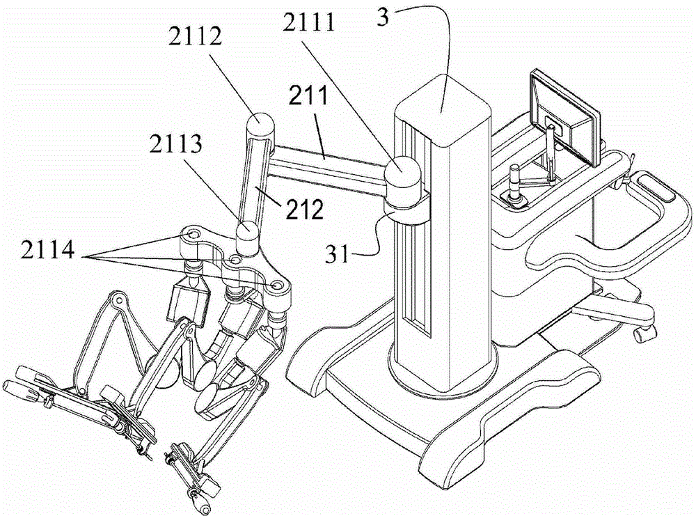
[0097] In an exemplary embodiment of the present invention, a positioning robot arm is provided. Please refer to figure 2 , the positioning robot arm includes seven parts: tail wheel a...


PUM


Abstract

The invention provides a positioning mechanical arm. The positioning mechanical arm comprises a tail pulley component (100), a big arm (200), a middle pulley component (300), a small arm (400), a front wheel component (500), a lifting arm (600) and a small connecting arm (700). A way of simultaneously locking a plurality of rotating joints through a band-type brake is adopted by the positioning mechanical arm, the limitation of locking single rotating joint through single band-type brake can be solved, accumulated gaps brought by the plurality of band-type brakes can be reduced, the integral quality of the mechanical arm can be reduced, and the operating precision can be improved.

Description

technical field [0001] The invention relates to the field of rotatable mechanical arms, in particular to a single brake multi-steel belt transmission positioning mechanical arm used for surgical positioning in medical equipment. Background technique [0002] As the incidence of vascular diseases such as cardiovascular and cerebrovascular diseases continues to rise, the utilization rate of minimally invasive vascular interventional surgery is also increasing. During minimally invasive vascular interventional surgery, it is necessary to feed tubes or wires into human blood vessels. The main function of the positioning robot arm is to fix the tube and wire feeding mechanism and make the tube and wire feeding mechanism reach the required spatial position. [0003] The positioning principle of existing positioning manipulators mostly uses brakes for positioning. When the brakes are energized and tightened, the corresponding rotary joints can rotate freely; when the brakes are de-...

Claims


Application Information

Patent Timeline
Patent Type & Authority Patents(China)
IPC IPC(8): A61B19/00
Inventor 王洪波杨雪侯增广胡国清曲新凯桑凌峰王云田振华武建双邓福海
Owner 唐山海容智能机器人科技有限公司
Why Eureka
Try Eureka