
A hepatic artery drug box indwelling catheter system

A hepatic artery and catheter technology, which is applied in the field of hepatic artery drug box indwelling catheter system, can solve the problems that restrict the widespread use, stimulation, and catheter tip displacement of percutaneous arterial drug box indwelling technology, so as to reduce catheter displacement and Risk of hepatic artery occlusion, improvement of success rate, effect of preventing catheter displacement

Active Publication Date: 2016-03-02
BEIJING CANCER HOSPITAL PEKING UNIV CANCER HOSPITAL
View PDF6 Cites 0 Cited by
  • Summary
  • Abstract
  • Description
  • Claims
  • Application Information

AI Technical Summary

Problems solved by technology

However, in the currently used method of percutaneous hepatic artery drug box implantation, the distal end hole of the indwelling catheter is located in the target vessel (proper hepatic artery), and chemotherapy drugs are perfused through the end hole of the indwelling catheter. The end hole perfusion method has the following disadvantages : (1) The distal part of the indwelling catheter is free in the hepatic artery, and the catheter head often shifts
Especially in patients with very short proper hepatic arteries, mild catheter displacement can lead to failure of perfusion chemotherapy
(2) The catheter head often collides with the wall of the hepatic artery, stimulating and damaging the hepatic artery, and the incidence of hepatic artery occlusion is high
(3) In the case of severe vascular variation or tortuousness, the technical success rate of end-hole perfusion is very low
The above shortcomings also restrict the widespread use of percutaneous arterial drug cartridge placement technology

Method used


Image

  • A hepatic artery drug box indwelling catheter system
  • A hepatic artery drug box indwelling catheter system

Examples


Embodiment Construction

[0020] The following embodiments are only used to illustrate the technical solutions of the present invention more clearly, and cannot be used to limit the protection scope of the present invention. For example, certain words are used in the specification and claims to refer to specific components. Those skilled in the art should understand that product manufacturers may use different terms to refer to the same component. This specification and claims do not use differences in names as a way to distinguish components, but use differences in functions of components as a criterion. The following description of the specification is a preferred embodiment for implementing the present invention. However, the description is for the purpose of explaining the general principles of the present invention and is not intended to limit the scope of the present invention. The protection scope of the present invention shall be subject to those defined by the appended claims.

[0021] The pres...


PUM


Abstract

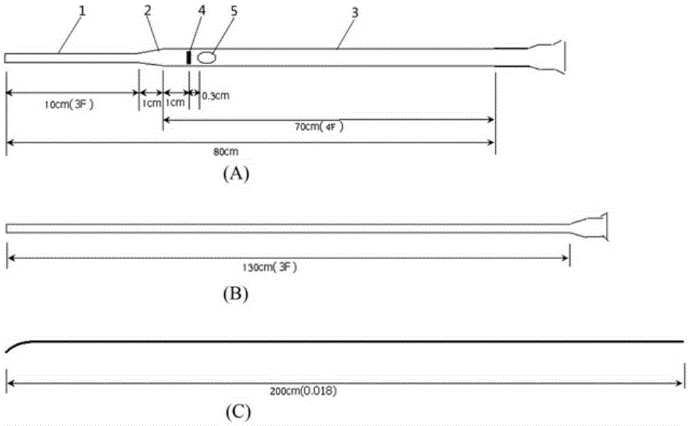
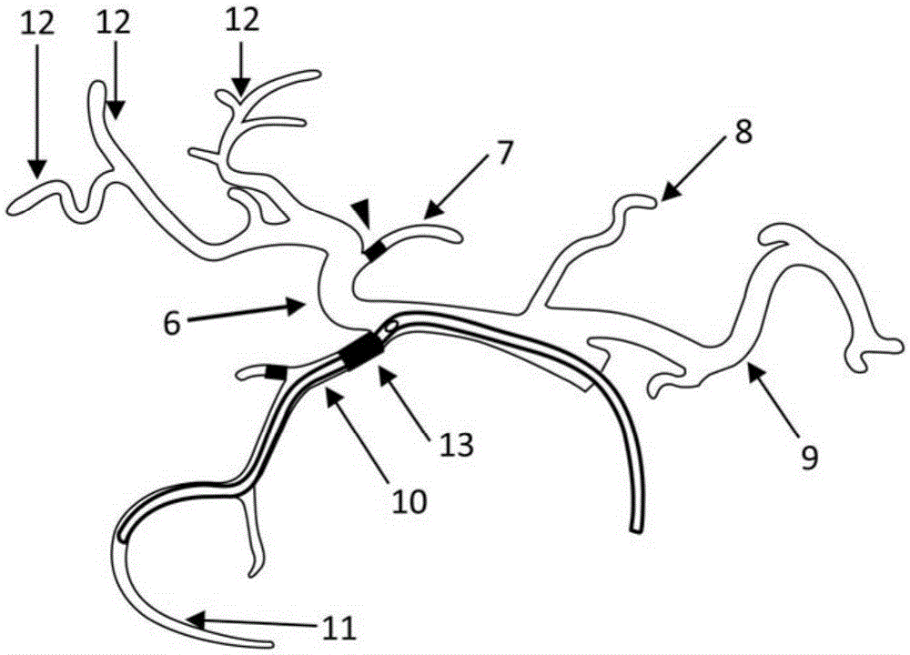
The invention relates to a hepatic artery medicine box retention catheter system which mainly comprises an in vivo retention catheter, a 2.6 to 3 F coaxial micro catheter and a micro guiding wire. The in vivo retention catheter comprises a far segment 2.6 to 3 F catheter, a near segment 4F catheter and a 2.6 to 3 F catheter and 4 F catheter connection part. An oval side hole is formed in the 4 F catheter and the short diameter of the side hole is slightly longer than the outer diameter of a cavity of the 2.6 to 3 F catheter. The length of the far segment 2.6 to 3 F catheter is 8 to 12 cm. By the adoption of the hepatic artery medicine box retention conduit system, the far segment of the retention catheter can enter the branch stomach omentum right artery of the gastroduodenal artery more easily, the far segment catheter is conveniently fixed, and filled medicine totally flows out of the side hole and an end hole does not need to be sealed. The filled medicine can enter and exit the micro catheter and the outer side of the retention catheter is fixed. The success rate of a hepatic artery medicine box retention catheter can be obviously improved, risks of catheter displacement and hepatic artery blocking are obviously reduced and the hepatic artery medicine box retention conduit system can be clinically and widely popularized and applied.

Description

Technical field [0001] The invention relates to a hepatic artery medicine box indwelling catheter system, in particular to a hepatic artery perfusion chemotherapy catheter medicine box indwelling system, in particular to a new type of unilateral approach, distal fixation, side hole perfusion, blocking prevention, and displacement prevention The arterial medicine box indwelling catheter system. Background technique [0002] Hepatic arterial chemotherapy is an internationally recognized treatment technique. Arterial chemotherapy, especially hepatic arterial chemotherapy, is significantly better than systemic intravenous chemotherapy. It is widely used in the treatment of colorectal cancer liver metastases and other liver malignancies. Regarding the establishment of the administration route of hepatic artery chemotherapy, there are two main types, one is the implantation of the hepatic artery kit under surgical laparotomy, and the other is the implantation of the hepatic artery kit ...

Claims


Application Information

Patent Timeline
Patent Type & Authority Patents(China)
IPC IPC(8): A61M25/00A61M25/04
Inventor 王晓东
Owner BEIJING CANCER HOSPITAL PEKING UNIV CANCER HOSPITAL
Learn More