Stirrer with high stirring strength and high shearing force

A technology of stirring strength and high shear force, applied in mixers with rotary stirring devices, chemical instruments and methods, dissolution and other directions, can solve the problems of energy waste, equipment idling loss, reduction of cylinder height-diameter ratio, etc. The effect of reducing energy consumption and operating costs, less maintenance failure points, and reducing labor intensity

Active Publication Date: 2014-06-25
CHANGSHA HASKY ENVIRONMENTAL PROTECTION TECH DEV CO LTD
View PDF4 Cites 9 Cited by
  • Summary
  • Abstract
  • Description
  • Claims
  • Application Information

AI Technical Summary

Problems solved by technology

[0002] Existing stirring devices are generally conveyed by electric motors through belt transmission or gear sets. The mechanical transmission structure of this type of stirring device is complex, and there are many additional equipment. At the same time, the energy consumption of the equipment is increased and the efficiency of the system is also reduced.
What is more prominent is that the torque of the ordinary motor is low, and it cannot drive the stirring device to stir the material with relatively high viscosity, strong stirring and strong shearing force, or the ideal stirring effect cannot be achieved.
In addition, most of the stirring devices cannot adjust the stirring torque and speed, resulting in the loss of equipment idling and the waste of energy consumption
In order to enhance the shear force of stirring, the methods currently used are generally by increasing the height-to-diameter ratio of th

Method used


Image

  • Stirrer with high stirring strength and high shearing force
  • Stirrer with high stirring strength and high shearing force
  • Stirrer with high stirring strength and high shearing force

Examples


Embodiment Construction

[0017] The present invention will be described in detail below in conjunction with the accompanying drawings.

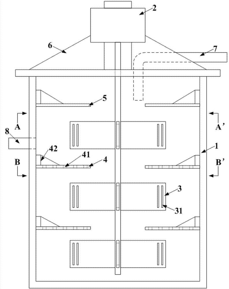
[0018] figure 1 It is a structural schematic diagram of an embodiment of the present invention, comprising a cylinder 1, a permanent magnet direct drive motor 2 and a feed inlet 7 are arranged on the top of the cylinder 1, the permanent magnet direct drive motor 2 is directly connected with the rotating shaft of the stirring paddle, and simultaneously The fixed bracket 6 fixes the permanent magnet direct drive motor 2 on the cylinder body 1, the control end of the motor is connected with the frequency conversion speed control machine, and the feeding port 7 is used for connecting with upstream equipment. The directly connected permanent magnet direct drive motor 2 greatly increases the torque of the agitator, while reducing energy consumption and maintenance costs.

[0019] After the fluid material enters the cylinder 1 through the feed port 7, it flows downward alo...


PUM


Abstract

The invention discloses a stirrer with high stirring strength and high shearing force. The stirrer comprises a barrel, a permanent magnetic direct-drive motor, an equipped variable-frequency speed adjuster, a shearing force stirring paddle, a barrel internal shearing force guide plate, a barrel top anti-splashing baffle plate, a fixed support, a feeding port and a discharging port. Compared with the existing stirring device, the stirring paddle, the guide plate and the guide plate with strong shear force and the permanent magnetic direct-drive motor with large torque are simultaneously utilized, so that the stirrer has the advantages of high stirring strength and strong shear force; meanwhile, the energy consumption and repairing cost of the stirring equipment can be reduced.

Description

technical field [0001] The invention relates to a high stirring intensity and high shear force stirrer. Background technique [0002] Existing stirring devices are generally driven by a motor through a belt drive or a gear set. The mechanical transmission structure of this type of stirring device is complex, and there are many additional equipment. At the same time, the energy consumption of the equipment is increased and the efficiency of the system is reduced. What is more prominent is that the torque of the ordinary motor is low, and it cannot drive the stirring device to stir the material with relatively high viscosity, which requires strong stirring and strong shearing force, or the ideal stirring effect cannot be achieved. In addition, most of the stirring devices cannot adjust the stirring torque and rotational speed, resulting in the loss of equipment idling and the waste of energy consumption. In order to enhance the shear force of stirring, the methods currently u...

Claims


Application Information

Patent Timeline
IPC IPC(8): B01F7/18
CPCY02P70/10
Inventor 孙伟唐鸿鹄刘文莉韩海生
Owner CHANGSHA HASKY ENVIRONMENTAL PROTECTION TECH DEV CO LTD
Why Eureka
Try Eureka