Environmental-protection waste gas heat exchange comprehensive utilization carbon drying kiln

An environmentally friendly, drying kiln technology, applied in drying, dryers, heating devices, etc., can solve problems such as air pollution, human health hazards, and inability to achieve, reduce energy consumption and operating costs, and save environmental protection costs , to achieve the effect of energy reuse

Pending Publication Date: 2019-08-23
沈林彬
View PDF0 Cites 0 Cited by
  • Summary
  • Abstract
  • Description
  • Claims
  • Application Information

AI Technical Summary

Problems solved by technology

[0002] Charcoal drying kiln is a large-scale drying equipment used for drying carbon materials. At present, the heat sources for drying carbon materials in major energy-consuming enterprises across the country use fluidized fluidized furnaces for drying work, while general fluidized fluidized furnaces use pulverized coal or coke The powder is burned to obtain heat, so the temperature in the fluidized furnace is above 800°C. If a fluidized furnace heat source above 800°C is used to dry the carbon material, the temperature above 800°C must be reduced to about 220-280°C to dry the carbon material. The reduction from 800°C to 220-280°C requires a large amount of normal temperature air to control the temperature, resulting in excessive oxygen emission from the exhaust gas after drying, causing the nitrogen oxide emission index to exceed the standard by more than 400mg / L, which cannot meet the new standards of the national environmental protection department. 150-200mg / L emission requirements, and excessive nitrogen oxides will cause serious air pollution, if inhaled by people, it will even cause harm to human health

Method used


Image

  • Environmental-protection waste gas heat exchange comprehensive utilization carbon drying kiln
  • Environmental-protection waste gas heat exchange comprehensive utilization carbon drying kiln
  • Environmental-protection waste gas heat exchange comprehensive utilization carbon drying kiln

Examples


Embodiment Construction

[0024] Below in conjunction with accompanying drawing and specific embodiment the present invention will be described in further detail:

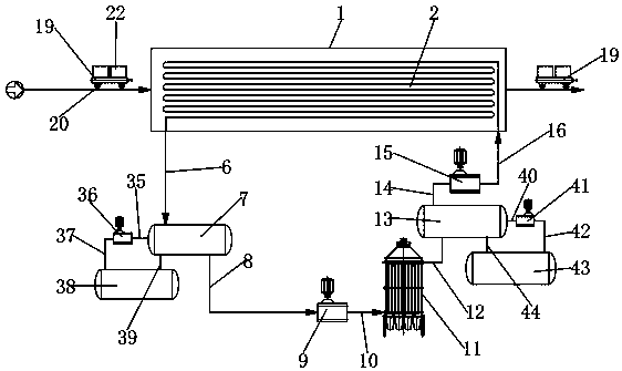
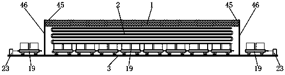
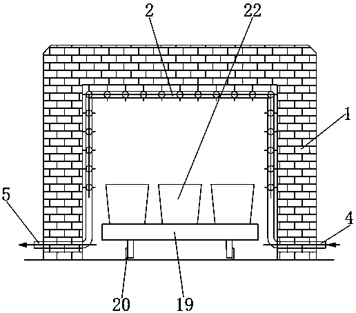
[0025] see Figure 1 to Figure 7 , the present invention provides an environment-friendly exhaust gas heat exchange comprehensive utilization charcoal drying kiln, comprising a tunnel-shaped heat exchange kiln 1, the inner wall of the heat exchange kiln 1 is provided with a disc-shaped oil pipe 2; the lower inner wall of the heat exchange kiln 1 A calcium carbide feeder track 3 is provided; a calcium carbide conveying device matching it is provided on the calcium carbide feeder track 3; a coil inlet 4 and a coil outlet 5 are respectively provided at both ends of the coiled oil pipe 2; The pipe outlet 5 is connected to a high-temperature heat-conducting oil storage tank 7 through a first high-temperature oil pipe 6; the high-temperature heat-conducting oil storage tank 7 is connected to the first oil pump 9 through a second high-temperature ...


PUM


Abstract

The invention discloses an environmental-protection waste gas heat exchange comprehensive utilization carbon drying kiln. The carbon drying kiln comprises a tunnel-shaped heat exchange kiln; a disc-shaped oil pipe is arranged on the inner wall of the heat exchange kiln; a calcium carbide car rail is arranged on the inner wall of the lower side of the heat exchange kiln; the calcium carbide car rail is provided with a matched calcium carbide conveying device; a coil inlet and a coil outlet are arranged at two ends of the disc-shaped oil pipe; the coil outlet is connected with a high-temperatureheat conducting oil storage tank through a first high-temperature oil pipe; the high-temperature heat conducting oil storage tank is connected with a first oil pump through a second high-temperatureoil pipe; the first oil pump is connected with a carbon drying kiln through a third high-temperature oil pipe; and the carbon drying kiln is connected with a low-temperature heat conducting oil storage tank through a first low-temperature oil pipe. The environmental-protection waste gas heat exchange comprehensive utilization carbon drying kiln needs no external air to control the temperature during drying of carbons to effectively prevent the condition of overproof emission index of nitrogen oxides.

Description

technical field [0001] The invention relates to a carbon material drying kiln, in particular to an environment-friendly exhaust gas heat exchange comprehensive utilization carbon material drying kiln. Background technique [0002] Charcoal drying kiln is a large-scale drying equipment used for drying carbon materials. At present, the heat sources for drying carbon materials in major energy-consuming enterprises across the country use fluidized fluidized furnaces for drying work, while general fluidized fluidized furnaces use pulverized coal or coke The powder is burned to obtain heat, so the temperature in the fluidized furnace is above 800°C. If a fluidized furnace heat source above 800°C is used to dry the carbon material, the temperature above 800°C must be reduced to about 220-280°C to dry the carbon material. The reduction from 800°C to 220-280°C requires a large amount of normal temperature air to control the temperature, resulting in excessive oxygen emission from the...

Claims


Application Information

Patent Timeline
IPC IPC(8): F26B15/16F26B23/10F26B25/06
CPCF26B15/16F26B23/10F26B25/063
Inventor 沈林彬廖昌斌王仙富
Owner 沈林彬
Why Eureka
Try Eureka