
Automatic pipeline cutting machine

A cutting machine and pipeline technology, which is applied in the field of automatic pipeline cutting machines, can solve the problems of low production efficiency, high cutting dust, and low automation, and achieve the effects of preventing accidental injury to workers, high processing efficiency, and strong automation

Inactive Publication Date: 2014-06-25
山耐斯气动液压(磐安)有限公司
View PDF0 Cites 16 Cited by
  • Summary
  • Abstract
  • Description
  • Claims
  • Application Information

AI Technical Summary

Problems solved by technology

With the use of pipe cutting machines, it is very convenient to cut pipelines. However, the pipe cutting machines in the prior art cannot be precisely lengthened and need to be fixed manually. The error is obvious, and there is a lot of cutting dust and noise. Workers in this environment Lower work will cause greater harm to it, low automation and low production efficiency

Method used

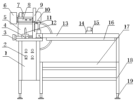
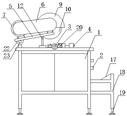
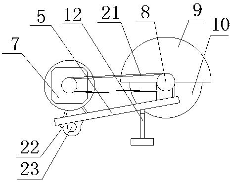

Image

  • Automatic pipeline cutting machine
  • Automatic pipeline cutting machine
  • Automatic pipeline cutting machine

Examples


Embodiment Construction

[0016] Such as figure 1 , 2 , 3, and 4, an automatic pipeline cutting machine includes a chassis 1, a pipe inlet port 3, a motor 7, and a cutting knife body 10. The right side of the chassis 1 is welded with a frame 18 with a receiving groove 17, and the chassis 1 There is a fixed block 4 on the top, the left end of the fixed block 4 is connected to the inlet pipe interface 3, and two runners 20 whose outer diameters are connected are installed on one side of the fixed block 4; The rocker 5 is inserted into the rotating rod 23 and fixedly connected with it. The other end of the rocker 5 is fixed on the chassis 1 through the lifting rod 12. The two ends of the rocker 5 are respectively installed with a motor 7 and a rotating shaft 8. The motor 7 is connected to the rotating shaft 8 through the pulley 21, and the rotating shaft 8 The other end is connected to the cutter body 10; the guide rail 13 is mounted on the chassis 1 and the frame 18, placed above the receiving groove 17...


PUM


Abstract

The invention discloses an automatic pipeline cutting machine comprising a case, an intake pipe joint, a motor and a cutter body. A frame with a receiving groove is welded on the right side of the case and a fixed block is arranged on the top of the case. The left side of the fixed block is connected with the intake pipe joint and two wheels with conterminous outside diameter are arranged on one side of the fixed block. A rotating rod is arranged on the case. A seesaw with a bump on one side is set into the rotating rod and connected with the rod. The other side of the seesaw is fixed on the case via a lift rod. The motor and a rotating shaft are respectively arranged on both ends of the seesaw, the motor is connected with the rotating shaft via a belt pulley and another end of the rotating shaft is connected with the cutter body. A slide way is arranged on the case and the frame, above the receiving groove. A stopper with an inductor is arranged on the slide way and an opening and closing plate is arranged on the bottom of the slide way. The automatic pipeline cutting machine has automatic transport and high precision, is saving in time and labor, strong in automation, good in safety, efficient in process, less in noise, and can reduce labor intensity and improve economic efficiency.

Description

technical field [0001] The invention relates to the technical field of pipeline cutting, in particular to an automatic pipeline cutting machine. Background technique [0002] As various pipelines play an important role in life, the output of many companies that produce pipelines is also increasing year by year. Before the appearance of pipe cutting machines, they were mainly cut by hand. The labor intensity of workers is extremely high, and the error is also large. Low benefit. With the use of pipe cutting machines, cutting pipelines has become very convenient. However, the pipe cutting machines in the prior art cannot be precisely fixed in length and need to be fixed manually. The error is obvious, and there is a lot of cutting dust and noise. The lower work is more harmful to it, the automation is low, and the production efficiency is low. content of the invention [0003] In order to solve the above problems, the object of the present invention is to provide an automa...

Claims


Application Information

Patent Timeline
Patent Type & Authority Applications(China)
IPC IPC(8): B23D21/00B23D33/02B23D33/10B23D33/00
Inventor 金光照
Owner 山耐斯气动液压(磐安)有限公司
Learn More