Method For Thermally Joining Non-round Functional Components To A Shaft

A non-circular and functional technology, applied to camshafts, heat-sealing cams in the field of camshafts, can solve problems such as high cost, complexity, and time constraints, and achieve the effects of increased connections, increased overlap, and high precision

Active Publication Date: 2014-06-25
MAHLE INT GMBH
View PDF11 Cites 1 Cited by
  • Summary
  • Abstract
  • Description
  • Claims
  • Application Information

AI Technical Summary

Problems solved by technology

This is complex, time-intensive and cost-

Method used


Image

  • Method For Thermally Joining Non-round Functional Components To A Shaft
  • Method For Thermally Joining Non-round Functional Components To A Shaft
  • Method For Thermally Joining Non-round Functional Components To A Shaft

Examples


Embodiment Construction

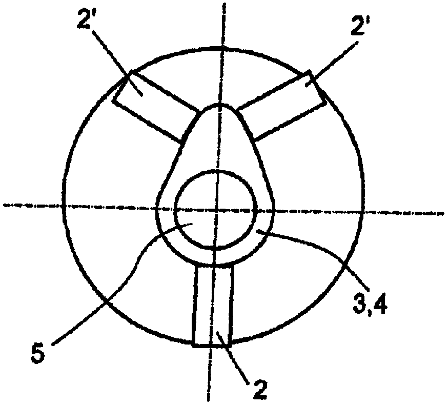
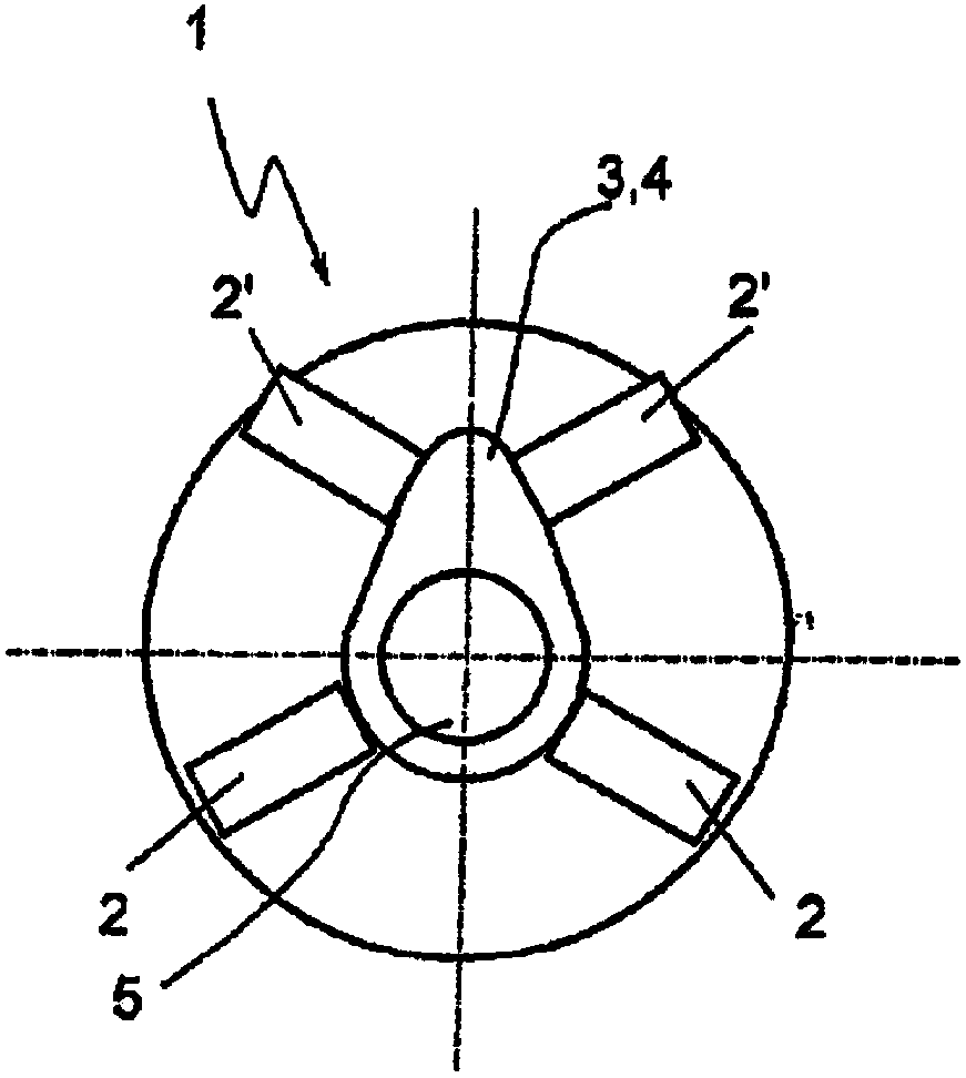
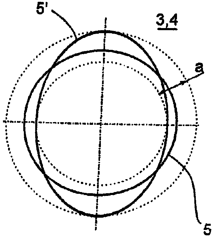
[0025] according to figure 1 and figure 2 , The claw-type clamp 1 has three or four claws 2, 2' for clamping a functional component 3, and the functional component in this example is a cam 4. The cam 4 is thus clamped in the jaw clamp 1 and elastically deformed at least slightly by the respective jaw 2, 2'. During this elastic deformation, especially compression, the through hole 5 is formed by drilling, grinding, reaming, turning or milling by a machine (not shown). The jaws 2, 2' are then moved into their starting position, whereby the clamped functional part 3 or cam 4 is relieved of stress. In the state of stress relief, due to elastic deformation, the through hole 5 becomes a non-circular through hole 5', and the through hole 5 is initially circular in the stress state, such as image 3 shown.

[0026] The cam 4 or generally the functional part 3 can now be heated and the corresponding shaft 6 or camshaft 7 can be cooled. During the heat sealing of the functional pa...


PUM


Abstract

The present invention relates to a method for thermally joining non-round functional components (3) to a shaft (6), especially a cam (4) thermal bonding on the camshaft (7) method.Which, through the functional unit in a round hole (5) in the process of making elastic compression, after the functional unit (3) remove the stress, the formation of a non circular hole (5'), and the functional unit (3) after bounding to the shaft (6) at least minimize the asymmetric deformation of the shaft (6).Thus can avoid don't expect asymmetric deformation of the shaft (6).

Description

technical field [0001] The invention relates to a method of heat sealing a non-circular functional part to a shaft, in particular a method of heat sealing a cam to a camshaft. The invention also relates to a non-circular functional part and at least one camshaft to which the non-circular functional part is thermally bonded. Background technique [0002] During the joining process of non-circular, asymmetrical functional parts, especially in the heat sealing process of the cam (pump cam or valve actuating cam) to the camshaft, due to the lateral compression and the Between the overlap, the camshaft will produce tube deformation in the functional part area (that is, the cam area). In cases where the bearing point is arranged in close proximity to the functional part, this can lead to deviations from circularity which are beyond the specification of a good bearing. In this case, the bearing points must be ground subsequently after joining the functional parts, which is an add...

Claims


Application Information

Patent Timeline
IPC IPC(8): B23P11/02B23P19/04B23P13/00
CPCF16B4/006F16H53/025F01L1/047B23P11/02B23P11/025F16D1/0858B23P2700/02Y10T29/49293
Inventor 克里斯托弗·贝伦斯弗兰克·多泰尔安东尼奥·梅农纳
Owner MAHLE INT GMBH
Why Eureka
Try Eureka