Industrial robot gripper with compact space, large clamping force and long stroke

An industrial robot with compact space technology, which is applied in the direction of manipulators, chucks, manufacturing tools, etc., can solve the problems affecting the stability and controllability of the transmission system, increasing the difficulty of industrial robot control, and the power cannot be transmitted normally, so as to achieve a compact structure , large driving force and small footprint

Active Publication Date: 2014-06-25
远洋探海机器人东台有限公司 +1
View PDF7 Cites 4 Cited by
  • Summary
  • Abstract
  • Description
  • Claims
  • Application Information

AI Technical Summary

Problems solved by technology

The jaws of the lever-type jaws are relatively swinging when they are working, and there are displacements in two rectangular coordinate directions. It is necessary to control the changes of the two coordinates at the same time, which increases the control difficulty of industrial robots.
Secondly, as the swing angle changes, the clamping force may also change, and it is not suitable for working environments that are sensitive to clamping force requirements.
[0004] Secondly, in an industrial environment, the space for grabbing and placing workpieces is often limited, and the length, width, and height of the mechanical gripper will affect the operation. Therefore, when opening and closing the gripper, it is necessary to minimize the occupied space, which requires The length of the rack itself should be shortened as much as possible, but the shortening of the rack will shorten the meshing distance with the driving gear, resulting in the failure of normal transmission of power, which will affect the stability and controllability of the transmission system of the mechanical gripper.

Method used


Image

  • Industrial robot gripper with compact space, large clamping force and long stroke
  • Industrial robot gripper with compact space, large clamping force and long stroke
  • Industrial robot gripper with compact space, large clamping force and long stroke

Examples


Embodiment Construction

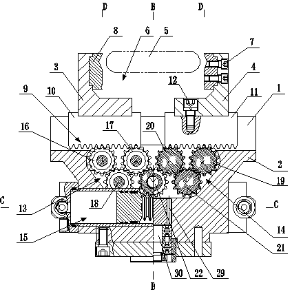
[0022] Below in conjunction with accompanying drawing and specific embodiment the present invention is described in further detail;

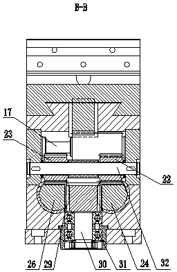
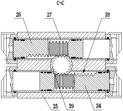
[0023] Such as figure 1 , 2 , 3, and 4, an industrial robot gripper with a compact space and a large long-stroke clamping force includes a frame body 2 with a slide rail 1, and the frame body 2 is provided with mutually sliding parts that can be slidably matched with the slide rail 1. Symmetrically arranged left gripper body 3 and right gripper body 4 form a gripping area 6 for gripping workpiece 5 between or on both sides of left gripper body 3 and right gripper body 4, left gripper body 3 and The right gripper body 4 can be made into a front-mounted outer clamping type, and can also be made into a reverse-mounted inner support type, and the clamping distance can be realized by adjusting the thickness of the left gripper body 3 and the right gripper body 4.

[0024] In order to improve the gripping effect, both the left gripper body 3 and the...


PUM


Abstract

The invention discloses an industrial robot gripper with compact space, large clamping force and a long stroke. The industrial robot gripper comprises a frame body provided with a sliding rail. A left gripper body and a right gripper body which are symmetric to each other and are in sliding fit with the sliding rail are arranged on the frame body. A grasping area used for grasping a workpiece is formed between the left gripper body and the right gripper body or grasping areas are formed at the two sides of the left gripper body and the right gripper body. The industrial robot gripper is characterized in that a left sliding base and a right sliding base which can be in sliding fit along the sliding rail are arranged in the length direction of the sliding rail, the bottom of the left sliding base and the bottom of the right sliding base are provided with racks, the left gripper body and the right gripper body are fixedly connected with the left sliding base and the right sliding base respectively, a first gear train and a second gear train which are in meshed fit with the two racks respectively are arranged inside the frame body, and a synchronous power device used for synchronously driving the two sliding bases to synchronously move in the opposite direction or the reverse direction is arranged between the first gear train and the second gear train. According to the industrial robot gripper, the stroke of the gripper bodies can be effectively lengthened, the two gripper bodies can synchronously move, and the central position of an object can be kept unchanged without the adjustment of the gripper.

Description

technical field [0001] The invention relates to the technical field of industrial robots, in particular to an industrial robot gripper with compact space, large clamping force and long stroke, which utilizes hydraulic pressure, pneumatic power and its auxiliary mechanisms to clamp workpieces. Background technique [0002] A manipulator is an automatic machine that simulates human hand operation. It can grasp and carry objects or manipulate tools to complete certain specific operations according to a fixed program. The application of manipulators can replace people in monotonous, repetitive or heavy physical labor, realize mechanization and automation of production, replace manual operations in harmful environments, improve working conditions, and ensure personal safety. Therefore, they are widely used in machinery manufacturing, metallurgy, and electronics. , light industry and atomic energy. In an industrial manufacturing environment, when using a manipulator to grab a lo...

Claims


Application Information

Patent Timeline
Patent Type & Authority Applications(China)
IPC IPC(8): B25J15/08
Inventor 王素刚
Owner 远洋探海机器人东台有限公司
Why Eureka
Try Eureka