
Multistage gas stripping and separating integrated anaerobic treatment device

The technology of an anaerobic treatment device and a gas-liquid separation tank, which is applied in the direction of anaerobic digestion and treatment, can solve the problems such as the influence of the service life of the gas-water separation tank, poor gas-liquid separation effect and efficiency, and impact on the inner wall of the gas-water separation tank. Achieve the effects of saving construction and land occupation costs, convenient operation, and fast gas-liquid circulation

Active Publication Date: 2015-05-20
山东许中华环保科技有限公司
View PDF4 Cites 0 Cited by
  • Summary
  • Abstract
  • Description
  • Claims
  • Application Information

AI Technical Summary

Problems solved by technology

Although the reactor has a secondary cycle, the flocculent sludge starts quickly and the granular sludge grows fast, but only the conical sludge expansion zone at the bottom can participate in the gas lift, the gas-liquid cycle is slow, and the mass transfer effect and wastewater treatment effect and efficiency need to be further improved
Moreover, the gas-solid-liquid is concentrated in the gas-solid-liquid separation area on the upper part of the cell body for separation, and the separation effect is poor.
In addition, the air bubbles in the gas-liquid will cause the phenomenon of "breathing" (gas-liquid flow intermittently) when the gas-liquid is running. Since the gas-liquid lifted by the stripper tube enters from the middle of the gas-water separation tank, the gas-liquid flow in the gas-water separation tank If this "breathing" phenomenon cannot be eliminated, it will cause impact on the inner wall of the gas-water separation tank, the effect and efficiency of gas-liquid separation will be poor, and it will also affect the service life of the gas-water separation tank

Method used


Image

  • Multistage gas stripping and separating integrated anaerobic treatment device
  • Multistage gas stripping and separating integrated anaerobic treatment device

Examples


Embodiment Construction

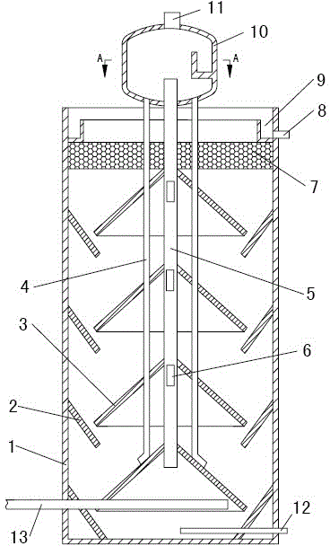
[0012] Such as figure 1 As shown, the multi-stage gas lift and separation integrated anaerobic treatment device of the present invention mainly includes a tank body 1 and a gas-liquid separation tank 10 , and the gas-liquid separation tank 10 is arranged on the top of the tank body 1 . The tank body 1 adopts a steel structure, the whole structure is columnar, and the upper end is open, and there are more than two sludge expansion gas lift areas ( figure 1 There are four in the middle picture, the number can be set according to specific requirements), and an anaerobic reaction zone is formed between the upper and lower sludge expansion and stripping zones. The sludge expansion airlift area is formed by an upwardly open falling bucket 2 and a downwardly open conical cover 3 arranged oppositely. The falling bucket 2 is arranged outside the conical cover 3 and fixed on the inner wall of the pool body 1. An upflow slot for the passage of muddy water is arranged between the conical...


PUM


Abstract

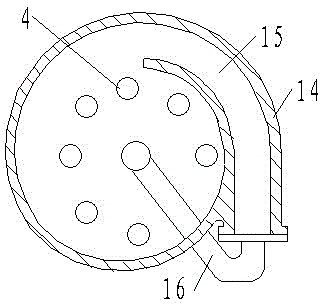
The invention discloses a multistage gas stripping and separating integrated anaerobic treatment device which comprises a pool body and a gas-liquid separation tank, wherein the gas-liquid separation tank is arranged at the top of the pool body; at least two conical sludge bulking areas are arranged in the pool body at intervals from top to bottom; a water distribution pipe is arranged at the bottom of the pool body; a gas stripping pipe and a return pipe are arranged in the pool body; the upper end of the gas stripping pipe stretches into the gas-liquid separation tank, and the lower end of the gas stripping pipe stretches into the lowest conical sludge bulking area; the gas stripping pipe is provided with a stripping port in each conical sludge bulking area; the upper end of the return pipe is connected with the bottom of the gas-liquid separation tank, and the lower end of the return pipe reaches the top of the lowest conical sludge bulking area; the gas-liquid separation tank is in the shape of a volute, and a liquid inlet and an exhaust port are formed in the gas-liquid separation tank. The device is provided with multistage gas-liquid stripping and gas-solid-liquid separation devices, the gas-liquid cycle is fast, the mass transfer efficiency is high, flocculent sludge is rapidly started, the granule sludge is rapidly increased, integrated multistage gas stripping and separating is realized, and the anaerobic treatment device is simple in operation, convenient to operate, low in treatment energy consumption, high in efficiency and stable in effluent quality.

Description

technical field [0001] The invention relates to an anaerobic reaction device used in the biochemical treatment stage of municipal and industrial wastewater treatment, and belongs to the technical field of anaerobic reaction treatment. Background technique [0002] Anaerobic reactions occur when wastewater and sludge particles come into contact. Biogas (mainly methane and carbon dioxide) produced under anaerobic conditions causes internal circulation, which is beneficial for the formation and maintenance of granular sludge. Some of the gas formed in the sludge layer is attached to the sludge particles, and the attached and unattached gases rise to the top of the reactor. The sludge rising to the surface hits the bottom of the gas emitter of the three-phase reactor, causing degassing of the sludge flocs with attached air bubbles. Various anaerobic reactors used for wastewater treatment at this stage can be classified as high, medium, and low-speed reactors, and anaerobic rea...

Claims


Application Information

Patent Timeline
Patent Type & Authority Patents(China)
IPC IPC(8): C02F3/28
Inventor 许中华
Owner 山东许中华环保科技有限公司
Learn More