Hollow fibers for adsorption or filtration and manufacturing method thereof
A fiber and hollow technology, applied in the field of hollow fiber and its production method, can solve the problem of not being suitable for filtering high-speed gas or liquid, etc.
- Summary
- Abstract
- Description
- Claims
- Application Information
AI Technical Summary
Problems solved by technology
Method used
Image
Examples
Embodiment 1 to 7
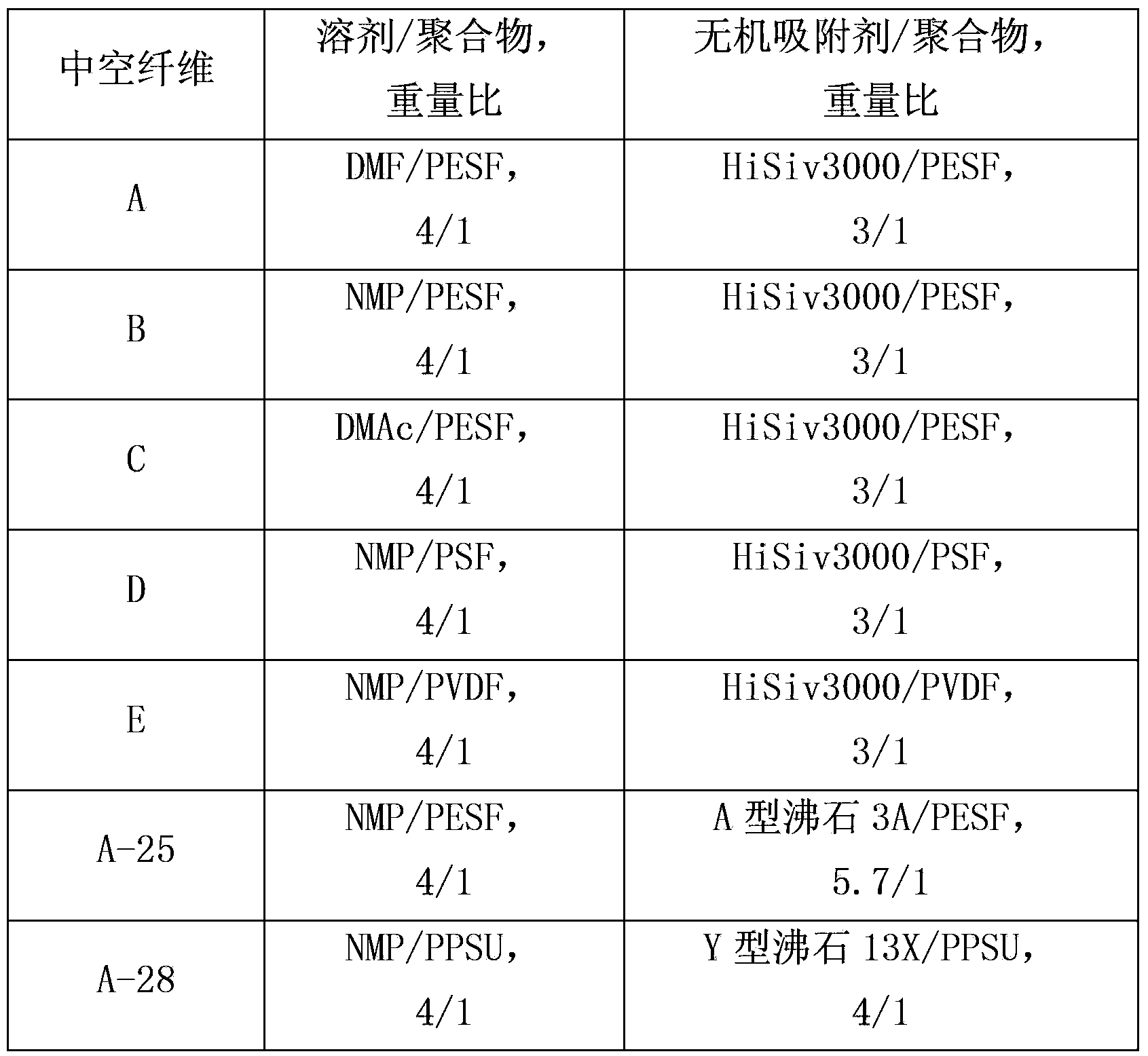
[0043] Seven hollow fibers A, B, C, D, E, A-25 and A-28 containing inorganic adsorbent were prepared as follows.
[0044] First, a spinning solution was prepared using a composition containing a solvent, a polymer, and an inorganic adsorbent as shown in Table 1 below.
[0045] Table 1. Spinning solution composition
[0046]
[0047] The polymer (100 grams (g)) was stirred in the solvent (400 to 500 milliliters (mL)) using a rotary pump at 100 rpm for 24 hours or until completely dissolved as a clear solution. Filter the solution. The inorganic adsorbent (400 to 700 g) was added slowly while stirring at 500 to 3000 rpm using an IKA Werke stirrer. The resulting mixture was stirred at the same speed for 6 to 48 hours. Then use a rotary pump to degas at 100 rpm for 24 to 48 hours to form a homogeneous spinning solution.
[0048] Hollow fibers were produced using the spinning dope thus prepared. Single-layer hollow fibers were produced using a tube-in-orifice spinneret havi...
Embodiment 8 to 10
[0055] Three double-layer hollow fibers C-12, C-16 and C-19 were prepared with the same procedure as above, but using two spinning dopes and using a tube body (diameter 0.8mm, chamfer angle 45°), Double-nozzle spinning head with inner nozzle (outer diameter 2mm, inner diameter 1.2mm) and outer nozzle (outer diameter 4mm, inner diameter 3mm).
[0056] Pressurize the first spinning solution in the first container to 2bar and let it pass through the inner nozzle
[0057] (orifice). The second spinning solution in the second vessel is pressurized to 2.5 to 3 bar and passed through an outer orifice. The hollow fibers formed from the first and second spinning solutions were subjected to the same post-treatment as above.
[0058] Hollow fibers C-12, C-16 and C-19 were manufactured according to these procedures:
Embodiment 8
[0059] In Example 8, hollow fiber C-12 was prepared from both the first spinning solution (13X / PESF, 10 / 1 by weight) and the second spinning solution (13X / PESF, 4 / 1 by weight). Use NMP as solvent, the dosage is 4 times of the weight of PESF.
PUM
| Property | Measurement | Unit |
|---|---|---|
| thickness | aaaaa | aaaaa |
| thickness | aaaaa | aaaaa |
| thickness | aaaaa | aaaaa |
Abstract
Description
Claims
Application Information
 - R&D
- Intellectual Property
- Life Sciences
- Materials
- Tech Scout
- Unparalleled Data Quality
- Higher Quality Content
- 60% Fewer Hallucinations
Browse by: Latest US Patents, China's latest patents, Technical Efficacy Thesaurus, Application Domain, Technology Topic, Popular Technical Reports.
© 2025 PatSnap. All rights reserved.Legal|Privacy policy|Modern Slavery Act Transparency Statement|Sitemap|About US| Contact US: help@patsnap.com


