
Enclosure protection system

A protection system and enclosure technology, applied in the field of enclosure protection systems, can solve the problems of high false alarm rate, inability to monitor around the clock, insensitive alarms, etc., and achieve the effects of excellent environmental resistance and convenient construction and maintenance.

Active Publication Date: 2014-06-25
ZHANGJIAGANG GOLDNET FENCING SYST
View PDF5 Cites 11 Cited by
  • Summary
  • Abstract
  • Description
  • Claims
  • Application Information

AI Technical Summary

Problems solved by technology

[0002] The existing fence protection system generally includes a fence or fence unit and an intrusion monitoring unit. The intrusion monitoring unit is used to monitor whether there are intruders or damage in the surrounding area. Or vibration sensors, although they can achieve simple defense functions, there are some disadvantages. For infrared sensors, the infrared beams are arranged to delineate the perimeter to be monitored. Whenever someone passes through the perimeter, the infrared beams are triggered. The temporary interruption of the system will start the alarm signal. The false alarm rate of this system is high. Plant leaves and small animals will cause infrared alarms, and there is no function to block the intrusion of personnel. For the electronic pulse rope, the electronic pulse rope is used to delineate the perimeter to be monitored. The electronic pulse scans each wire of the electronic wall 60 times per minute, and the peak value of each pulse is 5-8 kV, making it difficult for intruders to climb over. Such a system has a certain deterrent effect, but it cannot detect multiple intrusions , it is impossible to locate the intrusion location, and it cannot monitor around the clock; as for the vibration sensor, it is installed on the mesh or in the hollow column. The alarm is not sensitive when it is on the column, which will often cause false alarms

Method used


Image

  • Enclosure protection system
  • Enclosure protection system
  • Enclosure protection system

Examples


Embodiment Construction

[0021] Below in conjunction with the embodiment shown in the accompanying drawings, the present invention is described in detail as follows:

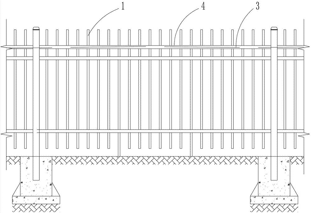
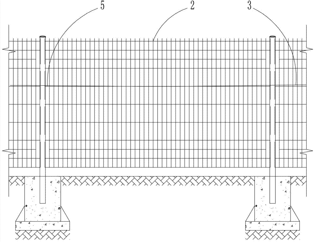
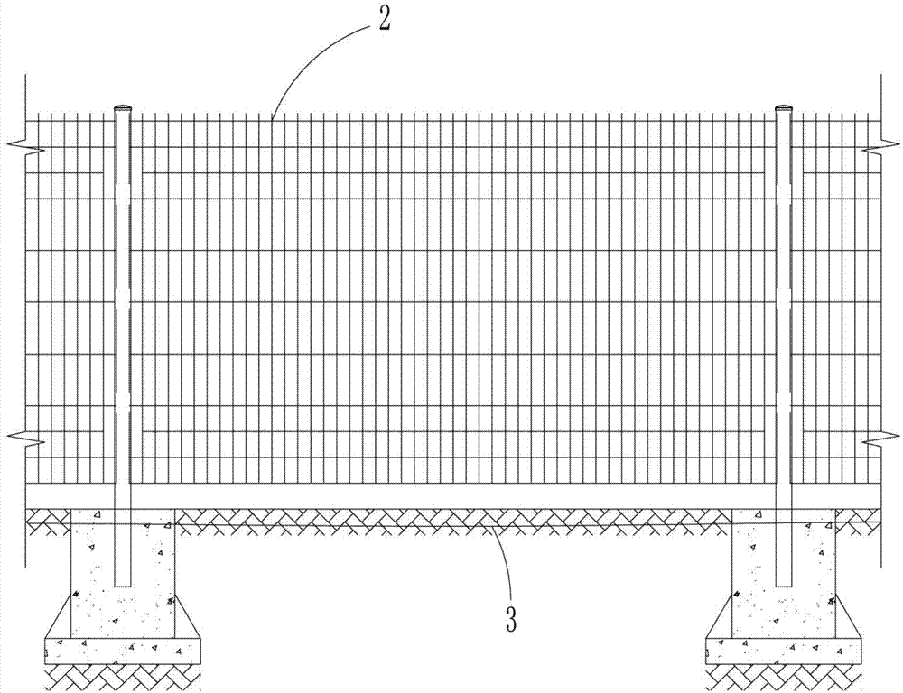
[0022] as attached figure 1 to attach Figure 5 As shown, a fence protection system includes a fence unit and an intrusion monitoring unit, the fence unit includes a fence 2 or a fence 1 arranged around the area to be protected, and the intrusion monitoring unit includes a perimeter set on the fence unit and / or Or the passive optical fiber 3 buried under the ground at the outer periphery of the enclosure unit, that is, the passive optical fiber 3 that is circumferentially arranged on the enclosure unit can be used alone, or the passive optical fiber 3 buried under the ground at the outer periphery of the enclosure unit can be used alone Passive optical fiber 3, or a combination of the above two methods, customers can choose according to their own needs, the upper end of the enclosure unit is provided with a hollow fiber protection tube...


PUM


Abstract

The invention discloses an enclosure protection system which comprises an enclosing and protecting unit and an invading monitoring unit, wherein the enclosing and protecting unit comprises a fence or a barrier which is arranged at the periphery of the area to be protected, and the invading monitoring unit comprises a passive optical fiber which is arranged on the enclosing and protecting unit in the circumference direction and / or is buried under the ground at the outer periphery of the enclosing and protecting unit. According to the design, the passive optical fiber is applied to monitor the outside invasion, and invasion mode and position are recognized to conduct systematic warning and real time alarm. Through the monitoring mode of the passive optical fiber, higher accuracy can be achieved in the large monitoring area or the long liner monitoring area, the optical fiber is excellent in environment resistance, monitoring accuracy is not affected by stormy weather and other severe environments, even cut off by an invader, the system is still capable of continuously providing effective alarm ability and will not fall into a paralyzed state, an external power, a repeater, a signal processor and other devices are not needed, and construction and maintenance are convenient and fast.

Description

technical field [0001] The invention relates to a perimeter protection system. Background technique [0002] The existing fence protection system generally includes a fence or fence unit and an intrusion monitoring unit. The intrusion monitoring unit is used to monitor whether there are intruders or damage in the surrounding area. Or vibration sensors, although they can achieve simple defense functions, there are some disadvantages. For infrared sensors, the infrared beams are arranged to delineate the perimeter to be monitored. Whenever someone passes through the perimeter, the infrared beams are triggered. The temporary interruption of the system will start the alarm signal. The false alarm rate of this system is high. Plant leaves and small animals will cause infrared alarms, and there is no function to block the intrusion of personnel. For the electronic pulse rope, the electronic pulse rope is used to delineate the perimeter to be monitored. The electronic pulse scans ...

Claims


Application Information

Patent Timeline
IPC IPC(8): E04H17/02E04H17/14G08B13/186
Inventor 宋国华徐律吴海刘海军季伟陆西湖
Owner ZHANGJIAGANG GOLDNET FENCING SYST
Learn More