Connection piece and refrigerator adopting same
A technology of connecting parts and connecting parts, which is applied in the field of parts and components, can solve problems such as frequent after-sales maintenance, cumbersome assembly parts, and weak connections, and achieve the effects of improving low efficiency, simple structure, and reducing production costs
- Summary
- Abstract
- Description
- Claims
- Application Information
AI Technical Summary
Problems solved by technology
Method used
Image

Examples
Embodiment 1
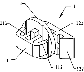
[0038] refer to Picture 1-1 As shown, a connector 1 includes a fixing part 11 and a connecting part 12 each having an elastic buckle structure. The spacer 13 is fixedly connected to the fixed part body 111 and the elastic buckles 112 on both sides of the fixed part body 111 , and the connecting part 12 is a long claw 121 .
[0039] One end of the long claw 121 is connected to the central part of the spacer 13 , and the other end is a cantilever end. A protrusion 122 facing the spacer 13 is provided at the end of the cantilever.
[0040] The connecting piece 1 is integrally injection molded.
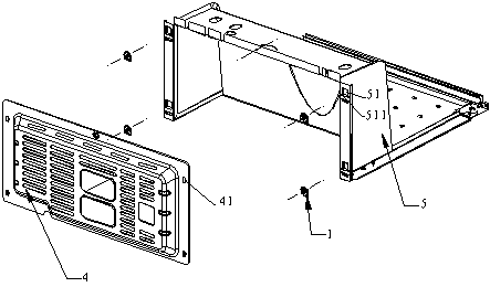
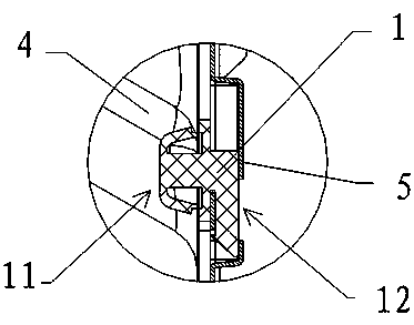
[0041] Such as Figure 1-2 As shown, the connecting piece 1 of the above-mentioned embodiment 1 is used to connect the compressor rear cover 4 and the compressor cabin 5 of the refrigerator. The matching clamping hole 41, the compressor cabin body 5 is provided with a connecting hole 51 adapted to the connecting part 12 of the connecting piece 1, and the connecting hole 51 is two upper...
Embodiment 2
[0044] refer to diagram 2-1 As shown, a connector 2 includes a fixing part 21 and a connecting part 22 each having an elastic buckle structure, and a disc-shaped spacer 23 between the fixing part 21 and the connecting part 22, wherein the fixing part 21 includes The spacer 23 is fixedly connected to the fixed part body 211 and the elastic buckles 212 on both sides of the fixed part body 211. The difference from Embodiment 1 is that the connecting part 22 is two symmetrically arranged short claws 221, and the short claws 221 are connected to On the spacer portion 23 , protrusions 222 opposite to each other are provided at non-connecting ends of the two short claws 221 .
[0045] The connecting piece 2 is integrally injection molded.
[0046] Such as Figure 2-2 As shown, in the exploded schematic diagram of the connection scheme for connecting the compressor rear cover 4 and the compressor cabin 5 of the refrigerator using the connector 2 of the above-mentioned embodiment 2,...
Embodiment 3
[0049] refer to Figure 3-1 As shown, a connector 3 includes a fixing part 31 and a connecting part 32 each having an elastic buckle structure, and a rectangular spacer 33 between the fixing part 31 and the connecting part 32, wherein the fixing part 31 includes a The spacer 33 is fixedly connected to the fixed part body 311 and the elastic buckles 312 on both sides of the fixed part body 311. The difference from Embodiment 1 is that the connecting part 32 is two asymmetric claws, including a long claw 321 and a Short jaws 322. Wherein, the long claw 321 and the short claw 322 are respectively connected to the edge of the spacer 33 , and the non-connecting end of the long claw 321 is provided with a protrusion 323 facing the short claw.
[0050] The connecting piece 3 is integrally injection molded.
[0051] Such as Figure 3-2 As shown, in the exploded schematic diagram of the connection scheme for connecting the compressor rear cover 4 and the compressor cabin 5 of the re...
PUM
 Abstract
Description
Claims
Application Information
 - R&D
- Intellectual Property
- Life Sciences
- Materials
- Tech Scout
- Unparalleled Data Quality
- Higher Quality Content
- 60% Fewer Hallucinations
Browse by: Latest US Patents, China's latest patents, Technical Efficacy Thesaurus, Application Domain, Technology Topic, Popular Technical Reports.
© 2025 PatSnap. All rights reserved.Legal|Privacy policy|Modern Slavery Act Transparency Statement|Sitemap|About US| Contact US: help@patsnap.com