
Slide valve type variable-damping shock absorber matched with air spring and working method thereof

A technology of air springs and shock absorbers, applied in the direction of springs/shock absorbers, shock absorbers, springs, etc., can solve the problems that affect the performance of the suspension system, the damping coefficient cannot be changed, and the damping force cannot be adjusted, so as to reduce costs , Improving passability and improving ride comfort

Inactive Publication Date: 2014-06-25
JIANGSU UNIV
View PDF6 Cites 16 Cited by
  • Summary
  • Abstract
  • Description
  • Claims
  • Application Information

AI Technical Summary

Problems solved by technology

[0006] 1. The single damping valve system makes the damping change value small, and the damping coefficient is not variable, which cannot achieve an ideal matching state with the non-linear stiffness air spring, which affects the effective performance of the suspension system.
[0007] 2. It is impossible to adjust the damping force in real time according to different driving conditions and loads, and it cannot form a coupling relationship with the air spring, which is independent of each other and has low reliability

Method used


Image

  • Slide valve type variable-damping shock absorber matched with air spring and working method thereof
  • Slide valve type variable-damping shock absorber matched with air spring and working method thereof
  • Slide valve type variable-damping shock absorber matched with air spring and working method thereof

Examples


Embodiment Construction

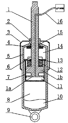
[0024] Referring to Fig. 1, the present invention contains a working cylinder 5 and a spool valve assembly, wherein the spool valve assembly includes a piston rod 1, a piston sleeve 7, a coil spring 12, an air bag spring 11, and a lower piston head 1a and an upper piston head 1b.

[0025] The piston rod 1 extends vertically downward from the center of the top of the working cylinder 5 in the inner cavity of the working cylinder 5. The inner cavity of the working cylinder 5 has a cylindrical piston sleeve 7, and the outer wall of the piston sleeve 7 and the inner wall of the working cylinder 5 There is a clearance fit between them, which can slide relative to each other. The lower end of the piston rod 1 is fixedly connected with the lower piston head 1a and the upper piston head 1b, and the piston rod 1, the upper piston head 1a, and the lower piston head 1b are regarded as a whole. The present invention has designed upper and lower piston heads, one is that the upper piston h...


PUM


Abstract

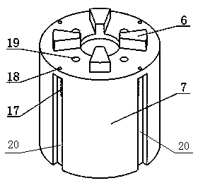
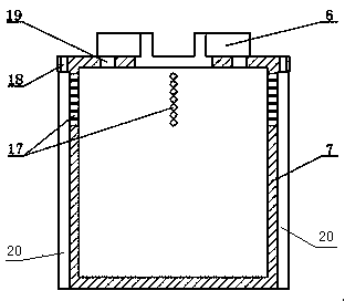
The invention discloses a slide valve type variable-damping shock absorber matched with an air spring and a working method thereof. The lower end of a piston rod is fixedly connected to an upper piston head and a lower piston head, the lower end face of the lower piston head is in close contact with an air bag spring, the upper end of the air bag spring is connected with the lower end of a gas conduit, the gas conduit protrudes upwards vertically through a hole in the center of the piston rod to stretch out of a working cylinder and then extends out of the lateral portion of the upper section of the piston rod to be connected with the air spring, a compensation air bag is placed on the bottom of an inner cavity of the working cylinder, four blind grooves are formed in the circumference of the outer wall of a piston sleeve at intervals of 90 degrees, the lower end of each blind groove is communicated with a lower cavity of the working cylinder, a sealed port is arranged between the upper end of each blind groove and the top face of the piston sleeve, several blind groove radial through holes arranged axially are formed in the upper portion of the interior of each blind groove, blind groove axial through holes communicated with the blind grooves and the blind groove radial through holes are formed in the positions of all the sealed ports of the top face of the piston sleeve, four piston sleeve axial through holes are evenly formed in the piston sleeve at intervals of 90 degrees and are located on the same radial positions with the blind groove axial through holes, and then the damping effect is guaranteed.

Description

technical field [0001] The invention relates to the field of vehicle suspension systems, in particular to an oil shock absorber used as an air spring and a damping element in the vehicle suspension system. Background technique [0002] The suspension system is one of the important components of the vehicle. Its function is to transmit all forces and moments between the wheels and the frame, and ease the impact load transmitted from the uneven road to the frame and body, and attenuate the load-bearing system caused by it. vibration to ensure the smooth running of the vehicle. [0003] The damping device and elastic elements in the suspension system have a great influence on the ride comfort of the vehicle, and often require lower damping and stiffness when unloaded, and greater damping and stiffness when fully loaded, and the difference between damping and stiffness The change needs to present a nonlinear relationship in order to meet the requirements of vehicle ride comfort...

Claims


Application Information

Patent Timeline
Patent Type & Authority Applications(China)
IPC IPC(8): F16F9/32F16F9/34
Inventor 李仲兴马孜立郭子权江洪
Owner JIANGSU UNIV
Learn More