Device and method for dust collection and discharge of sintering flue gas

The technology of a sintering flue gas and ash discharge device, which is applied in the field of sintering flue gas treatment, can solve the problems of ash accumulation and clogging in the main pipe of circulating flue gas, and achieve remarkable ash discharge effect, which is beneficial to dust removal, and the ash discharge method is simple and practical

Active Publication Date: 2015-06-17
MCC NORTH (DALIAN) ENG TECH CO LTD
View PDF9 Cites 0 Cited by
  • Summary
  • Abstract
  • Description
  • Claims
  • Application Information

AI Technical Summary

Problems solved by technology

[0003] The purpose of the present invention is to provide a sintering flue gas ash collection and ash discharge device and method to solve the problem of ash accumulation and blockage in the main pipe of the circulating flue gas in the existing sintering flue gas circulation process

Method used


Image

  • Device and method for dust collection and discharge of sintering flue gas
  • Device and method for dust collection and discharge of sintering flue gas
  • Device and method for dust collection and discharge of sintering flue gas

Examples


Embodiment Construction

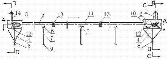
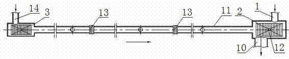
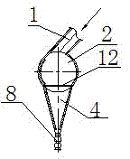
[0027] As shown in the figure, the sintering flue gas ash collection and ash discharge device is composed of the nose dust collection pipe 2 and the tail dust collection pipe 3 connected by the connecting pipe 5, which are used to connect the nose bellows and the nose dust collection pipe. The air intake pipe I1 between 2, the air intake pipe II14 used to connect between the tail air box and the tail dust collection pipe 3, the dust below the dust collection pipe 2 of the machine head and the dust collection pipe 3 of the tail respectively Collecting bucket 4, multiple dust collecting buckets 6 arranged on the connecting pipe 5, flue gas outlet pipe 10 arranged on the dust collecting pipe 2 of the machine head, and the grating plate walking set in the dust collecting bucket 4 The platform 12, the double-layer ash unloading valve 8 located under the dust collection bucket 4, the ash discharge pipe 7 connected to the bottom of the dust collection bucket 6, and the single-layer he...


PUM


Abstract

The invention relates to a device and method for dust collection and discharge of sintering flue gas. The device is characterized in that the device comprises a machine head dust collection pipe, a machine tail dust collection pipe, a gas inlet pipe I, a gas inlet pipe II, large dust collection hoppers, small dust collection hoppers and a flue gas outlet pipe, wherein the machine head dust collection pipe and the machine tail dust collection pipe are communicated through a connecting pipe, the large dust collection hoppers are arranged below the machine head dust collection pipe and the machine tail dust collection pipe respectively, the small dust collection hoppers are arranged on the connecting pipe, the flue gas outlet pipe is arranged on the machine head dust collection pipe, the gas inlet pipe I is connected to the top of the machine head dust collection pipe in the tangential direction, and the gas inlet pipe II is connected to the top of the machine tail dust collection pipe in the tangential direction. After flue gas flows into the machine head dust collection pipe and the machine tail dust collection pipe through the gas inlet pipe I and the gas inlet pipe II in the tangential direction, the flue gas moves axially in a spirally rotary mode, and dust is collected and discharged respectively through the large dust collection hoppers and the small dust collection hoppers. The device for dust collection and discharge is simple and reasonable in structure, the method for dust collection and discharge of the device is simple and practical, the application value is high, the purpose of exhaust dust treatment of a machine head air box and a machine tail air box can be effectively achieved, and the dust collecting effect and the dust discharging effect are remarkable.

Description

technical field [0001] The invention relates to a sintering flue gas treatment technology in the metallurgical industry, in particular to a sintering flue gas ash collection and ash discharge device and method. Background technique [0002] During the sintering production process, a large amount of hot flue gas will be generated. The flue gas generated in the traditional sintering process enters the main dust reduction pipe from the bellows, and is discharged from the main extraction system. In the sintering flue gas circulation process, a part of the flue gas from the bellows will be selected to participate in the sintering process again. If the sintering flue gas in the wind boxes at the head and tail of the sintering machine is selected for circular sintering, the flue gas in the wind box at the nose and the tail wind box must be collected into a circulating flue gas The gas is sent into the main pipeline, and then sent to the dust collector by the main pipeline. After t...

Claims


Application Information

Patent Timeline
Patent Type & Authority Patents(China)
IPC IPC(8): F27D17/00
Inventor 张志刚郑绥旭闫为群
Owner MCC NORTH (DALIAN) ENG TECH CO LTD
Why Eureka
Try Eureka