Tensile clamp of belt vulcanized joint and tensile tester of horizontal belt vulcanized joint

A tensile testing machine and fixture technology, applied in the direction of applying stable tension/pressure to test the strength of materials, measuring devices, instruments, etc., can solve the problem that the effectiveness of belt joints cannot be detected, and the tensile strength test of joints cannot be carried out. To ensure safe transportation and other issues, to achieve the effect of low production cost and test cost, simple structure and convenient operation

Inactive Publication Date: 2014-06-25
HENAN COAL SCI RES INST
View PDF13 Cites 5 Cited by
  • Summary
  • Abstract
  • Description
  • Claims
  • Application Information

AI Technical Summary

Problems solved by technology

The existing clamps have the following disadvantages: for coal mine transportation, the mechanical tensile strength at the vulcanized joint of the belt can reach 90% of the normal part, and there is a large difference in height and poor stability. It is the weakest link in the belt, and it is also Frequently broken areas
Due to the long length of the belt joint, which is about 1350-6650mm, the current traditional tensile machinery does not have enough space, and the clamping jaws are short and narrow. As a result, the tensile strength test of the joint cannot be carried out, and the belt joint cannot be realized at all. Effectiveness testing, it can not guarantee safe transportation

Method used


Image

  • Tensile clamp of belt vulcanized joint and tensile tester of horizontal belt vulcanized joint
  • Tensile clamp of belt vulcanized joint and tensile tester of horizontal belt vulcanized joint
  • Tensile clamp of belt vulcanized joint and tensile tester of horizontal belt vulcanized joint

Examples


Embodiment 1

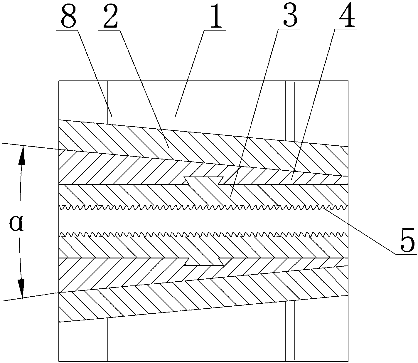
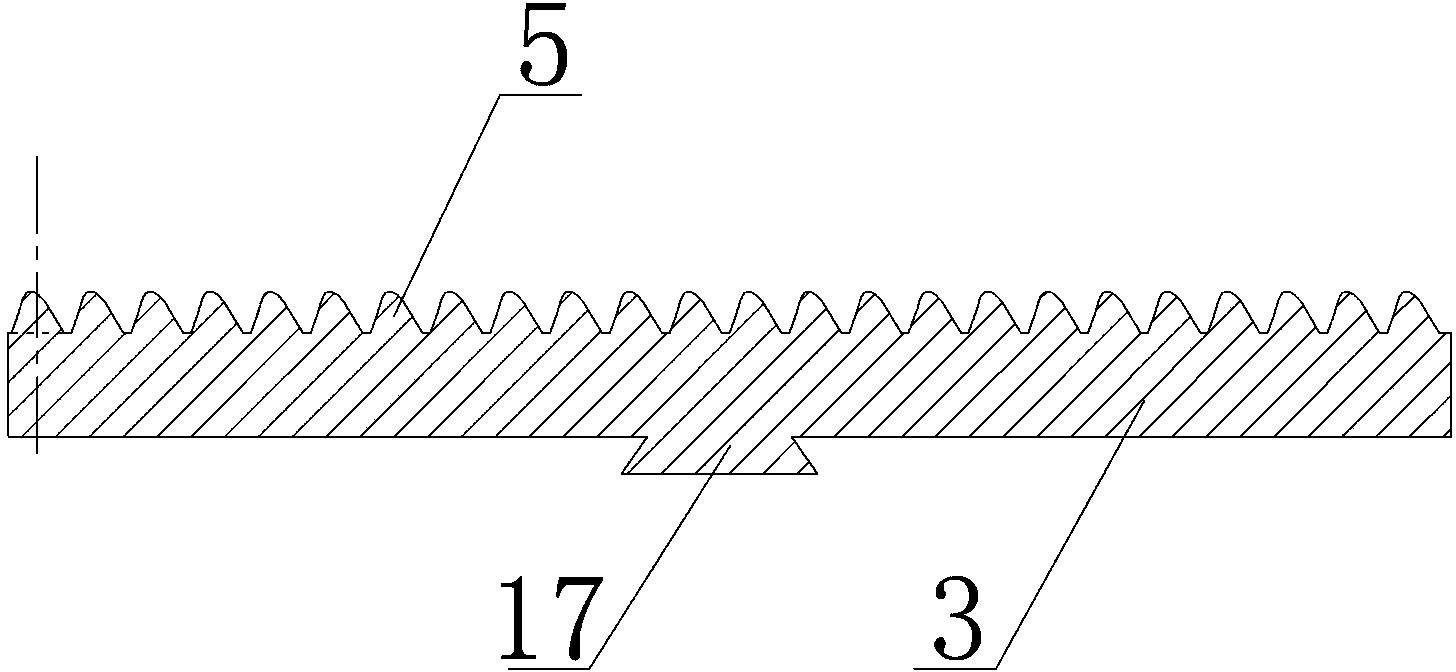
[0030] Embodiment one: see figure 1 — image 3 , Figure 6 , a tension fixture for belt vulcanized joints, including a bottom plate 1, two vertical plates 2 vertically fixed on the bottom plate 1, a wedge-shaped slide plate 4 and a clamping block 3, the angle between the inner surfaces of the two vertical plates 2 is α , and 9°≤α≤18°, the tops of the two vertical vertical plates 2 are fixed with connecting plates, the two sides of the vertical plates 2 are fixed with reinforcing plates 8, and two symmetrical wedge-shaped slide plates 4 are respectively matched and attached to the two vertical plates 2 on the inner surface, and the inner surfaces of the two wedge-shaped slides 4 are parallel to each other, and the inner surface of each wedge-shaped slide 4 and the clamping block 3 are connected together through the matching structure of the vertically arranged dovetail groove 16 and the dovetail strip 17, The inner surface of the clamping block 3 is uniformly provided with cl...

Embodiment 2

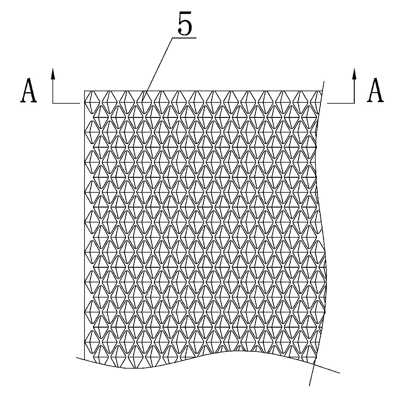
[0031] Embodiment two: see Figure 1-Figure 3 , Figure 6 , the structure of this embodiment is basically the same as that of Embodiment 1, and the similarities will not be repeated. The difference is that the bottom of the clamping protrusion 5 on the inner surface of the clamping block 3 is rhombus-shaped, and the rhombus-shaped The smaller apex angle is 55° or 60° or 65°, and the clamping convex teeth 5 are arranged in a rhombus grid.

Embodiment 3

[0032] Embodiment three: see Figure 1-Figure 7 , a horizontal belt vulcanized joint tensile testing machine, bolts are pre-embedded in the reinforced concrete ground, the strip base 9 is fixed on the pre-embedded bolts, and the fixed tensile fixture on the left side and the The movable stretching fixture on the right side is fixed with a bearing 11 on the right side base 9 of the movable stretching fixture,

[0033] The right side of the support 11 is fixedly equipped with a power unit through evenly distributed claws 10, and the power unit is a jack 20, or a hydraulic cylinder or an air cylinder. The output end on the right side of the power unit is connected to the pressure sensor 12, and the pressure The sensor 12 is fixedly connected to the load-bearing top plate 13 vertically arranged on its right end, and the two sides of the load-bearing top plate 13 are connected with the two sides of the movable stretching fixture through symmetrical pull rods 14, and the base 9 on t...


PUM

PropertyMeasurementUnit
angleaaaaaaaaaa
lengthaaaaaaaaaa

Abstract

The invention discloses a tensile clamp of a belt vulcanized joint and a tensile tester of a horizontal belt vulcanized joint. The clamp comprises a bottom plate, two vertical plates, two wedge slide plates and a clamping block, wherein the two vertical plates are vertically fixed on the bottom plate; the included angle between the inner surfaces of the two vertical pates is alpha; alpha is smaller than or equal to 18 and greater than or equal to 9; the two symmetrical wedge slide plates are respectively matched and attached to the inner surfaces of the two vertical plates; the inner surfaces of the two wedge slide plates are parallel; the inner surface of each wedge slide plate is connected with the clamping block through a matched structure of a vertically arranged dovetail groove and a dovetail strip; clamping convex teeth are evenly distributed on the inner surface of the clamping block; the top ends of the clamping convex teeth slightly incline backwards; slide chutes are formed in the lower parts of the wedge slide plates and / or clamping block; roller chains are placed inside the slide chutes. The tensile clamp is simple in structure, convenient to operate, energy-saving, environment-friendly, safe, and low in cost, the tensile clamp can be prevented from slipping when stretching, and the belt can be prevented from being locally crushed.

Description

technical field [0001] The invention relates to a detection device for a belt vulcanized joint used in mines, in particular to a tensile fixture for a belt vulcanized joint and a horizontal belt vulcanized joint tensile testing machine. Background technique [0002] In the field of material tensile testing, the sample must be reliably clamped to prevent slipping, so that the technical parameters such as tensile strength, yield strength, elongation, residual stress, and elastic modulus of the material can be accurately obtained. The existing clamps have the following disadvantages: for coal mine transportation, the mechanical tensile strength at the vulcanized joint of the belt can reach 90% of the normal part, and there is a large difference in height and poor stability. It is the weakest link in the belt, and it is also The site where broken belts often occur. Due to the long length of the belt joint, which is about 1350-6650mm, the current traditional tensile machinery do...

Claims


Application Information

Patent Timeline
Patent Type & Authority Applications(China)
IPC IPC(8): G01N3/04G01N3/08
Inventor 傅泉臻
Owner HENAN COAL SCI RES INST
Why Eureka
Try Eureka