Impedance measurement system and impedance measurement method of a secondary battery
A secondary battery, impedance measurement technology, applied in the direction of measuring electrical variables, measuring resistance/reactance/impedance, measuring electricity, etc., can solve the problems that the full impedance of the battery cannot be measured, the polarization impedance does not have time to change, and the accuracy of the measurement results is not high.
- Summary
- Abstract
- Description
- Claims
- Application Information
AI Technical Summary
Problems solved by technology
Method used
Image
Examples
Embodiment 1
[0039] Example 1: AC impedance test method of secondary battery during charging operation,
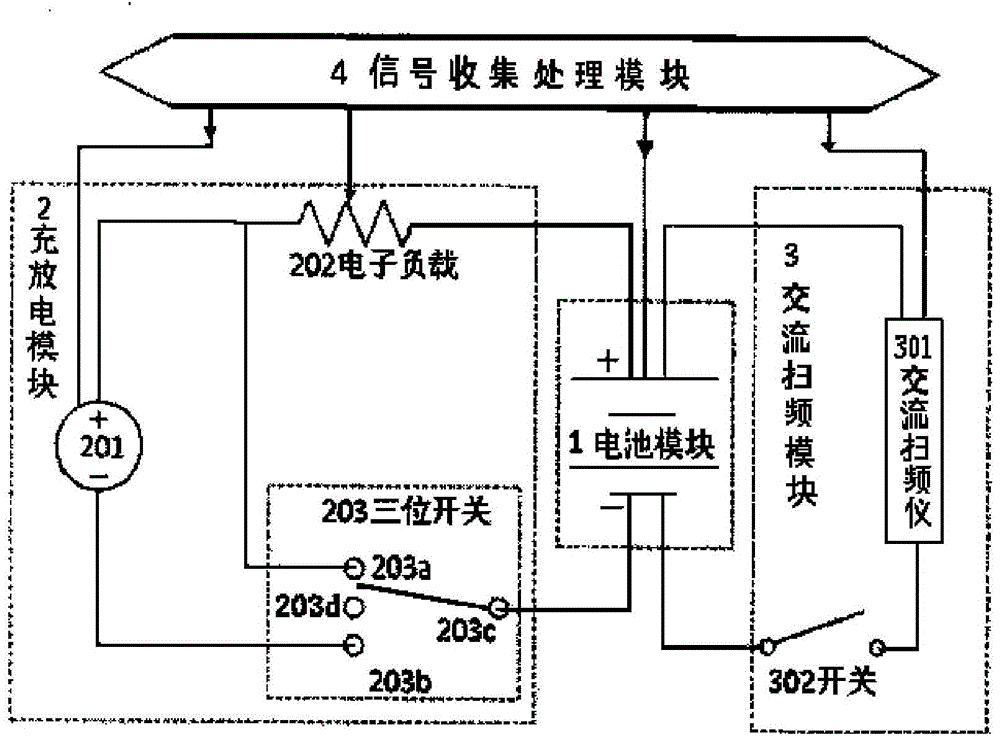
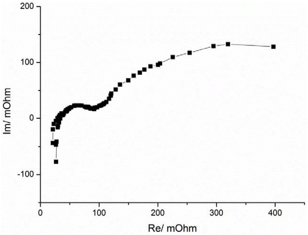
[0040] Such as figure 1 As shown, this embodiment includes a battery module 1, a charging and discharging module 2, an AC frequency sweeping module 3, and a signal collection and processing module 4. The 203c point of the 203 three-position switch in the charging module 2 is connected to the negative electrode of the battery module 1, and the 201 stable power supply, the electronic load 202 and the positive electrode of the battery module 1 are connected through the 203b point to form a complete DC charging circuit; the AC frequency sweep module The 302 switch contained in 3 is closed, so that the battery module 1, the 301 AC sweeper and the 302 switch form an AC test loop. The signal collection and processing module 4 controls the 201 stable power supply and the 202 electronic load, so that the battery module 1 operates at the specified stable DC constant current charging, and controls t...
Embodiment 4
[0042] Example 2: AC impedance test method of secondary battery during discharge operation
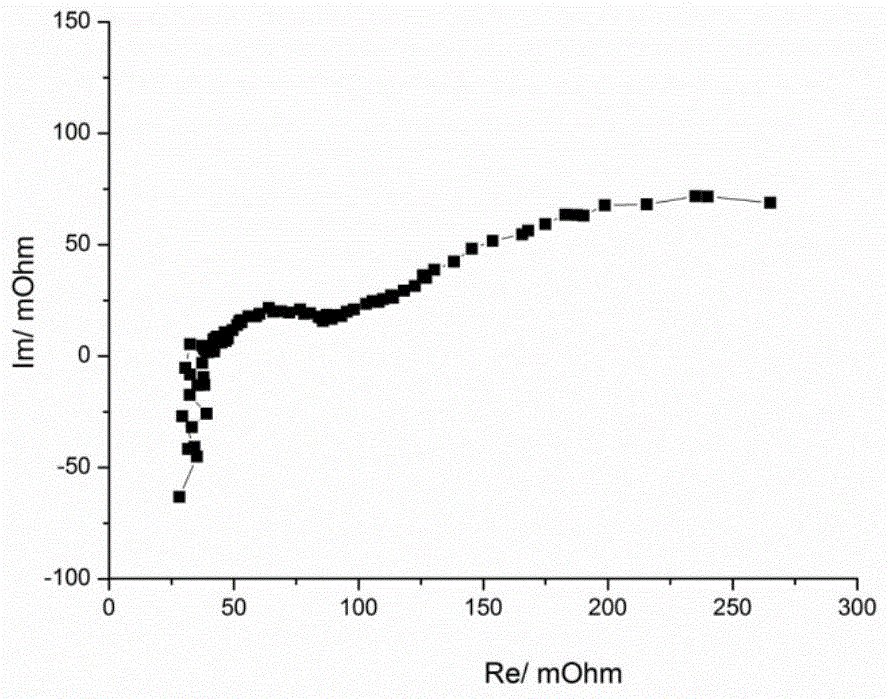
[0043] Such as figure 1 As shown, this embodiment includes a battery module 1, a charging and discharging module 2, an AC frequency sweeping module 3, and a signal collection and processing module 4. The 203c point of the 203 three-position switch in the charging module 2 is connected to the negative electrode of the battery module 1, and the negative electrode of the battery module 1 is connected to the 202 electronic load and the positive electrode of the battery module 1 through the 203a point of the 203 three-position switch to form a complete DC discharge circuit The 302 switch contained in the AC sweep module 3 is closed, so that the battery module 1, the 301 AC sweeper and the 302 switch form an AC test loop. The signal collection and processing module 4 controls the 202 electronic load so that the battery module 1 operates at a prescribed stable DC constant current charging operat...
PUM
 Abstract
Description
Claims
Application Information
 - R&D
- Intellectual Property
- Life Sciences
- Materials
- Tech Scout
- Unparalleled Data Quality
- Higher Quality Content
- 60% Fewer Hallucinations
Browse by: Latest US Patents, China's latest patents, Technical Efficacy Thesaurus, Application Domain, Technology Topic, Popular Technical Reports.
© 2025 PatSnap. All rights reserved.Legal|Privacy policy|Modern Slavery Act Transparency Statement|Sitemap|About US| Contact US: help@patsnap.com


