Induction energy taking power source of electric transmission line monitoring device

A technology for monitoring equipment and transmission lines, applied in circuit devices, battery circuit devices, current collectors, etc., can solve problems such as the inability to control energy absorption CT energy absorption, difficult installation, complex insulation problems, etc., to enhance the load capacity and Adaptability, ensure lasting and stable operation, and reduce the effect of calorific value

Active Publication Date: 2014-06-25
CHONGQING UNIV +2
View PDF7 Cites 19 Cited by
  • Summary
  • Abstract
  • Description
  • Claims
  • Application Information

AI Technical Summary

Problems solved by technology

If the voltage dividing capacitor is a grounding capacitor, complex insulation problems need to be considered, and there are few applications; if the voltage dividing capacitor is a spatially distributed capacitor, because the spatially distributed capacitor is weak, it needs to meet the energy harvesting requirements. Larger dimensions and difficult installation
CT energy harvesting and power supply is a "self-sufficient" online energy harvesting and power supply method that uses the principle of electromagnetic induction to directly intercept energy from the electromagnetic

Method used


Image

  • Induction energy taking power source of electric transmission line monitoring device
  • Induction energy taking power source of electric transmission line monitoring device
  • Induction energy taking power source of electric transmission line monitoring device

Examples


Embodiment Construction

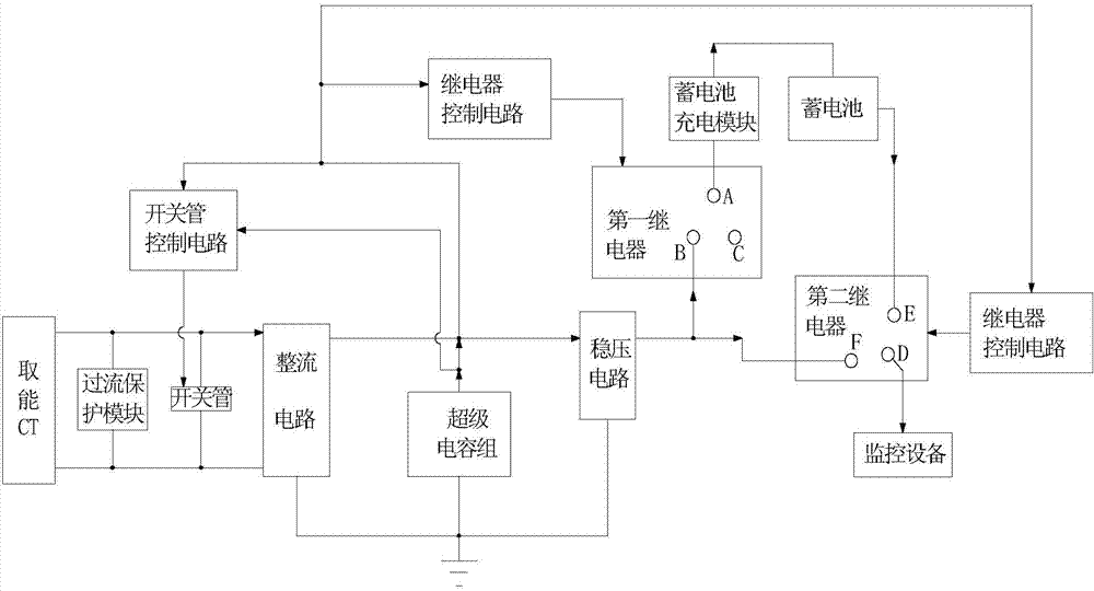
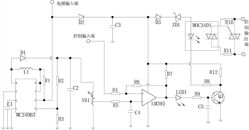
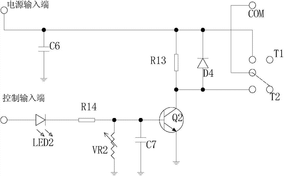
[0017] figure 1 It is a block diagram of the present invention, figure 2 It is the schematic diagram of the relay control circuit of the present invention, image 3 It is a schematic diagram of the switching tube control circuit of the present invention, Figure 4 It is a functional block diagram of the battery charging module of the present invention. As shown in the figure, an inductive energy harvesting power supply for transmission line monitoring equipment provided by the present invention includes an energy harvesting CT coupled to the transmission line for obtaining electric energy from the transmission line, and The protection unit electrically connected to the output end of the energy-taking CT, the rectification circuit electrically connected to the output end of the energy-taking CT, the energy storage unit electrically connected to the output end of the rectification circuit, and the on-off control unit; the rectification circuit The output terminal is also elec...


PUM


Abstract

The invention provides an induction energy taking power source of an electric transmission line monitoring device. The induction energy taking power source comprises an energy taking CT, a protection unit, a rectifying circuit, an energy storage unit and an on-off control unit, wherein the energy taking CT is arranged on an electric transmission line in a coupled mode and used for obtaining electric energy from the electric transmission line, the protection unit is electrically connected with the output end of the energy taking CT, the rectifying circuit is electrically connected with the output end of the energy taking CT, and the energy storage unit is electrically connected with the output end of the rectifying circuit. The output end of the rectifying circuit is further electrically connected with the input end of the monitoring device, the energy storage unit is further electrically connected with the input end of the monitoring device, the on-off control unit is used for controlling a power supply access between the rectifying circuit and the monitoring device and a power supply access between the energy storage unit and the monitoring device to be connected or disconnected, a power circuit can be effectively prevented from being burnt by excessive absorbed energy of the energy taking CT under the large current of the electric transmission line, the heating amount of the power source is reduced, the redundant absorbed energy is effectively stored, insufficient power supply, caused by the condition that the current of the electric transmission line is a small current or the electric transmission line is powered off, of the monitoring device can be avoided, and it is guaranteed that the energy taking power source can output the stable direct current to the monitoring device.

Description

technical field [0001] The invention relates to a power supply, in particular to an inductive energy harvesting power supply for power transmission line monitoring equipment. Background technique [0002] The power supply of transmission line online monitoring equipment can be roughly divided into three categories according to the power supply mode, namely, solar panel and battery coordinated power supply, laser power supply, capacitor voltage divider power supply and CT induction energy harvesting power supply. Although solar panel and battery coordinated power supply is a method that is widely used in line online monitoring equipment at present, this method is easily affected by the weather (especially in the south where there are many rainy weather, so it is not applicable) and it completely relies on battery power supply at night. Low reliability. The laser power supply method has no electrical connection between the high-voltage side and the low-voltage side, and the p...

Claims


Application Information

Patent Timeline
IPC IPC(8): H02J17/00H02J7/02H02J50/00
Inventor 熊兰周健瑶杨子康谢兵伍福平陈峥王微波
Owner CHONGQING UNIV
Why Eureka
Try Eureka