image transmission device

A transmission device and image technology, applied in the field of image processing, can solve the problems of transmission image size limitation, increase product cost, etc.

Active Publication Date: 2017-06-13
GUANGDONG VTRON TECH CO LTD
View PDF7 Cites 0 Cited by
  • Summary
  • Abstract
  • Description
  • Claims
  • Application Information

AI Technical Summary

Problems solved by technology

The method adopted at this stage is generally to encode the image signal through the video encoding chip and send it to the video decoding chip of another processing unit. The video decoding chip decodes the signal for local signal processing. This method usually requires additional video encoding and decoding. chip, which increases the cost of the product, and the size of the transmitted image is limited by the bandwidth of the video codec chip

Method used


Image

  • image transmission device
  • image transmission device
  • image transmission device

Examples


Embodiment Construction

[0015] In order to make the purpose, technical solution and advantages of the present invention more clear, the present invention will be further described in detail below in conjunction with the accompanying drawings and embodiments. It should be understood that the specific embodiments described here are only used to explain the present invention, and do not limit the protection scope of the present invention.

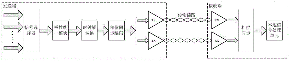
[0016] The structure of the image transmission device of the present invention is as follows figure 1 As shown, the multiple image signals at the sending end are sent through the signal selector, and the selected image signal is input to the polarity unification module. Due to different input signal sources, the polarity of the vertical synchronization signal and the horizontal synchronization signal of the image signal It may be different. In order to facilitate the back-end signal processing, it is necessary to convert the vertical synchronization signal and horizo...


PUM


Abstract

The invention discloses an image transmission device, which adopts multiple high-speed serial transceivers to simultaneously transmit one image signal. Since the bandwidth requirements of the high-speed serial transceivers are not high, a low-bandwidth high-speed serial transceiver can be used for transmission. Compared with the way of video codec chip transmission, the cost is reduced. When the input image data bandwidth is high, such as ultra-high-definition resolution signals, 3D signals, etc., the transmission can be completed by increasing the number of high-speed serial transceivers. The device also performs phase synchronization encoding on the image signal at the sending end, and adopts corresponding measures at the receiving end to ensure phase synchronization between multiple transceivers, so as to avoid blurred screen phenomenon caused by image data misalignment.

Description

technical field [0001] The invention relates to the technical field of image processing, in particular to an image transmission device. Background technique [0002] In the field of image processing, it is often necessary to transfer image signals from one processing unit to another. The method adopted at this stage is generally to encode the image signal through the video encoding chip and send it to the video decoding chip of another processing unit. The video decoding chip decodes the signal for local signal processing. This method usually requires additional video encoding and decoding. The chip increases the cost of the product, and the size of the transmitted image is limited by the bandwidth of the video codec chip. Contents of the invention [0003] Based on the above situation, the present invention proposes an image transmission device to reduce the cost of image transmission while ensuring the transmission quality. To this end, the adopted scheme is as follows...

Claims


Application Information

Patent Timeline
Patent Type & Authority Patents(China)
IPC IPC(8): H04N5/38H04N5/44H04N5/04
Inventor 胡庆荣
Owner GUANGDONG VTRON TECH CO LTD
Why Eureka
Try Eureka