Device for controlling brake lights in a motor vehicle

A technology for brake lights and motor vehicles, which is applied in the direction of foot-operated starting devices, braking transmission devices, braking action starting devices, etc., and can solve problems such as errors

Active Publication Date: 2016-06-01
ROBERT BOSCH GMBH
View PDF6 Cites 0 Cited by
  • Summary
  • Abstract
  • Description
  • Claims
  • Application Information

AI Technical Summary

Problems solved by technology

In this case, the immobility is produced, for example, by the fact that the above-described plausibility test fails, for example, when starting the motor or changing gears, if no brake pedal signal is available.

Method used


Image

  • Device for controlling brake lights in a motor vehicle
  • Device for controlling brake lights in a motor vehicle
  • Device for controlling brake lights in a motor vehicle

Examples


Embodiment Construction

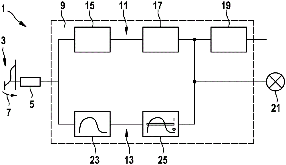
[0030] figure 1 A circuit diagram of a device for controlling brake lights in a motor vehicle according to an exemplary embodiment of the invention is shown schematically. The device 1 has a brake pedal sensor 5 arranged on a brake pedal 3 . Depending on the intensity with which the brake pedal 3 is actuated by pressure along the arrow 7, the brake pedal sensor 5 emits a quantitative brake pedal signal which is dependent on the actuation intensity and transmits it to an electronic control Unit (ECU) 9 on. There, the brake pedal signal is routed not only to a main control unit 11 but also to a backup control unit 13 .

[0031] The main control device 11 is used, for example, in an electric vehicle or a hybrid vehicle to detect the operating strength of the brake pedal 3 and to control or adjust a brake according to the driver's braking demand corresponding to the brake pedal operation. moving process. For this purpose, main control unit 11 has a hardware circuit 15 and a so...


PUM


Abstract

A device (1) for controlling a brake light (21) of a motor vehicle is described. The device comprises a brake pedal sensor (5), a main control device (11) and a reserve control device (13). The brake pedal sensor (5) outputs a brake pedal signal which is dependent on an activation intensity of a brake pedal (3). The main control device (11) conditions and monitors the brake pedal signal and generates a brake control signal for controlling a braking process. In addition, the main control device (11) generates a brake pedal activation signal for controlling activation of the brake light. While the main control device (11) can be implemented by means of software in some of its functions, the reserve control device (13) is implemented exclusively by means of hardware and uses a comparator (25) to carry out a comparison between a brake pedal signal conditioned with a component (23) and switch-on and switch-off thresholds for the activation of the brake light. With the device proposed it is possible to dispense with conventionally used brake light switches and at the same time to ensure that even in the case of a defect in the main control device (11) a brake pedal activation signal is reliably generated which can both correctly activate the brake light (21) and prevent the vehicle from becoming stranded.

Description

technical field [0001] The invention relates to a device for controlling brake lights in a motor vehicle. The invention also relates to a motor vehicle equipped with such a device. Background technique [0002] A mechanical brake light switch is usually used for actuating the brake light in a vehicle. The stop lamp switch is mounted on a pedal device of a vehicle and can detect operation of a brake pedal. In this case, the brake light switch generates a brake pedal signal, which merely indicates that the brake pedal is actuated or not actuated. That is, the brake pedal signal recognizes only two states: not actuated (="0") and actuated (="1"). In this case, the brake pedal signal is used to control the activation of the brake light, that is to say to switch the brake light on or off. [0003] In addition, some vehicle manufacturers use the brake pedal signal additionally for safety queries, in certain situations, for example in the case of an automatic transmission, when...

Claims


Application Information

Patent Timeline
Patent Type & Authority Patents(China)
IPC IPC(8): B60Q1/44B60T7/04B60T13/66
CPCB60T7/042B60Q1/44B60Q1/441B60Q11/002B60T13/662B60T17/22
Inventor M.孔斯M.比克T.施佩里
Owner ROBERT BOSCH GMBH
Why Eureka
Try Eureka