
Uncoiling straightening machine special for fine blanking

A straightening machine and fine blanking technology, applied to other manufacturing equipment/tools, accessories of shearing machines, shearing devices, etc., can solve the axial limit of steel coils, inconvenient adjustment of the gap between the upper and lower rolls, poor straightening quality, etc. question

Inactive Publication Date: 2014-07-02
广州卡司顿机电技术有限公司
View PDF6 Cites 22 Cited by
  • Summary
  • Abstract
  • Description
  • Claims
  • Application Information

AI Technical Summary

Problems solved by technology

However, when the steel coil is installed in the equipment, it is difficult to stably and reliably axially limit the steel coil only by the pressing device
[0003] In addition, the correction of the existing uncoiling straightening machine is mainly realized by the straightening roller. The straightening roller in the straightening mechanism is one of the important parts of the straightening process, but the existing straightening roller is generally fixed in design, so it is not convenient to adjust the upper and lower rollers. The gap between will affect the quality of correction
Moreover, the quality of straightening is directly related to the arrangement of straightening rollers, and the existing straightening rollers are all evenly distributed, so the quality of straightening is not good.

Method used


Image

  • Uncoiling straightening machine special for fine blanking
  • Uncoiling straightening machine special for fine blanking
  • Uncoiling straightening machine special for fine blanking

Examples


Embodiment Construction

[0038] The present invention will be further described in detail below with reference to the accompanying drawings and specific embodiments.

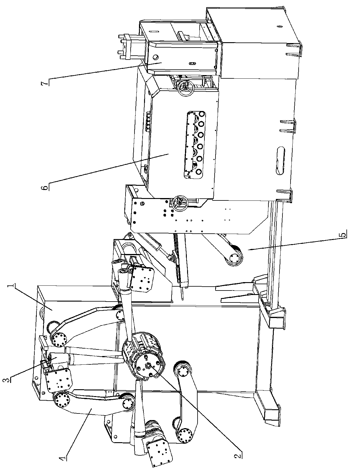
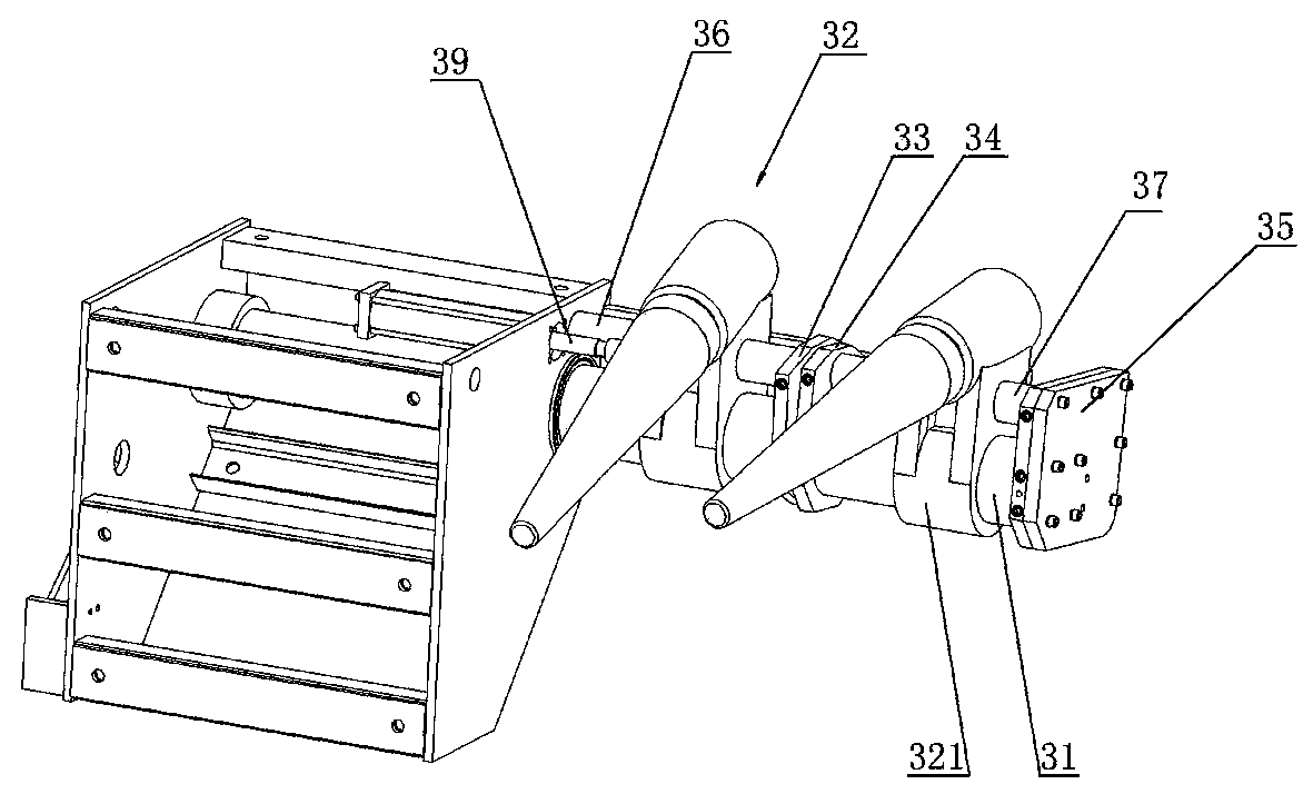
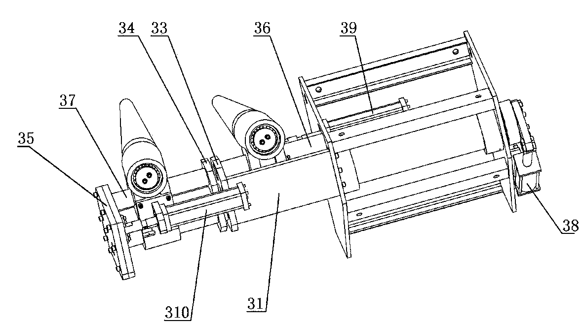
[0039] like Figure 1 to Figure 4 As shown, the special uncoiler straightening machine for fine blanking includes an uncoiler frame 1 , a material frame 2 , a material blocking mechanism 3 , a material pressing mechanism 4 , a material guiding mechanism 5 , a rectifying mechanism 6 , and a shearing mechanism 7 .

[0040] like Figure 5 and Image 6 As shown, the uncoiling frame 1 includes a bottom plate 11 , a base frame 12 and a column 13 . The bottom plate 11 is welded to the bottom of the base frame 12, and a first reinforcing rib plate 14 is welded between the bottom plate 11 and the base frame 12 to improve the connection strength between the bottom plate 11 and the base frame 12, thereby improving the uncoiling frame. The base frame 12 includes a transverse beam 121 and a longitudinal beam 122, and the longitudinal beam 122 is ...


PUM


Abstract

The invention discloses an uncoiling straightening machine special for fine blanking. The uncoiling straightening machine special for fine blanking comprises an uncoiling rack, a material frame, a material blocking mechanism, a material pressing mechanism, a material guiding mechanism, a straightening mechanism and a shearing mechanism. The material blocking mechanism comprises a material blocking arm assembly which comprises an extending arm and a material blocking arm. The front section of the material blocking arm is in the shape of a frustum or a cone. The diameter of the end, close to the material frame, of the material blocking arm is smaller than the diameter of the end, away from the material frame, of the material blocking arm. The straightening mechanism comprises a straightening rack, lower straightening rollers and upper straightening rollers. The lower straightening rollers which are arranged transversely are arranged on the straightening rack. A third sliding groove is formed in the straightening rack, and a third sliding block is arranged in the third sliding groove. The upper straightening rollers are arranged on the third sliding block, an adjusting device is arranged on the straightening rack, the distance between every two adjacent lower straightening rollers is gradually reduced, and the distance between every two adjacent upper straightening rollers is gradually reduced. By means of the structure of the uncoiling straightening machine special for fine blanking, coil stock loaded on the material frame can be reliably and axially limited, the material blocking arm can be prevented from being abraded fast, the straightening quality can be improved, and the uncoiling straightening machine special for fine blanking is suitable for straightening of belt materials with different thicknesses.

Description

technical field [0001] The present invention relates to an unwinding straightening machine. Background technique [0002] In the stamping and forming process, strips are generally used, but for transportation requirements, the strips are usually coils before stamping. Therefore, the coils need to be uncoiled and corrected before stamping. Now there is a special uncoiler leveling machine. For example, in the patent document with the authorization announcement number CN202655900U whose application date is 2012.7.19 and the authorization announcement date is 2013.1.9, a fully automatic CNC steel plate uncoiler leveling device is disclosed, including Leveling machine and CNC shearing machine, the upper part of the steel coil is provided with a pressing device, and the front end of the pressing device is provided with an automatic steel plate tie shearing device; a downwardly inclined self-driven material guide is arranged above the steel coil. The shovel head oil cylinder is hi...

Claims


Application Information

Patent Timeline
Patent Type & Authority Applications(China)
IPC IPC(8): B21D1/02B23D15/04B23D33/00B23P23/00
Inventor 廖向东毛家鑫贺骢
Owner 广州卡司顿机电技术有限公司
Learn More