Supercharge Your Innovation With Domain-Expert AI Agents!

Mouth-shaped beam connecting device of composite wing and fuselage

A technology of composite materials and connecting devices, which is applied in the direction of fuselage, aircraft parts, transportation and packaging, etc., can solve the problems of increasing the tolerance of bolts and holes, large amount of machine addition, and waste of materials, so as to reduce the connection weight and facilitate Effects of processing and improving reliability

Inactive Publication Date: 2014-07-02
HARBIN INST OF TECH
View PDF5 Cites 0 Cited by
  • Summary
  • Abstract
  • Description
  • Claims
  • Application Information

AI Technical Summary

Problems solved by technology

Among them, the number of bolts for distributed force transmission in the peripheral connection is relatively large. The advantage is that the force transmission efficiency of the skin at the root of the wing is fully utilized, and no special complicated connection joints are required, which is conducive to reducing the weight of the structural design. The disadvantage is that the wing-body connection is increased. The assembly workload is heavy, and the tolerance between the bolt and the hole must be increased, which will adversely affect the transmission of shear force and fatigue strength
Concentrated force transmission is to connect the wing and the fuselage with several points, which can transmit large force and moment, reduce the assembly man-hours of connecting the wing and the fuselage, and can make the wing-body joint into one, so that The beam is not only the connecting member between the wing and the wing body, but also the load-bearing support point for the external wing and internal loading; its disadvantages are mainly that the benefits of the root skin cannot be fully utilized, the amount of machine addition is large, and there is a lot of material waste

Method used


Image

  • Mouth-shaped beam connecting device of composite wing and fuselage
  • Mouth-shaped beam connecting device of composite wing and fuselage
  • Mouth-shaped beam connecting device of composite wing and fuselage

Examples


Embodiment Construction

[0016] The technical solution of the present invention will be further described below in conjunction with the accompanying drawings, but it is not limited thereto. Any modification or equivalent replacement of the technical solution of the present invention without departing from the spirit and scope of the technical solution of the present invention should be covered by the present invention. within the scope of protection.

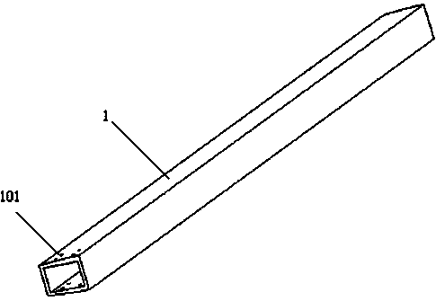
[0017] figure 1 The mouth-shaped beam 1 of the present invention is given, wherein the mouth-shaped beam 1 is formed by composite material layup, because there is a potential difference between the carbon fiber and the metal material, galvanic corrosion will occur, so the inner layer is a stripped fiber layup, The outside is a carbon fiber layup. There are several holes-101 on the upper and lower edge strips at one end of the mouth-shaped beam 1.

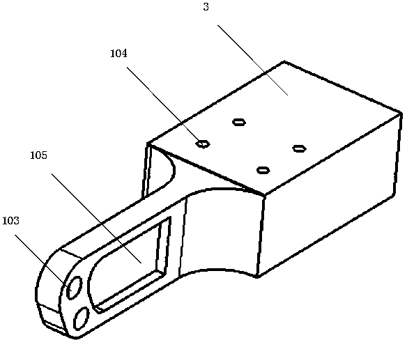
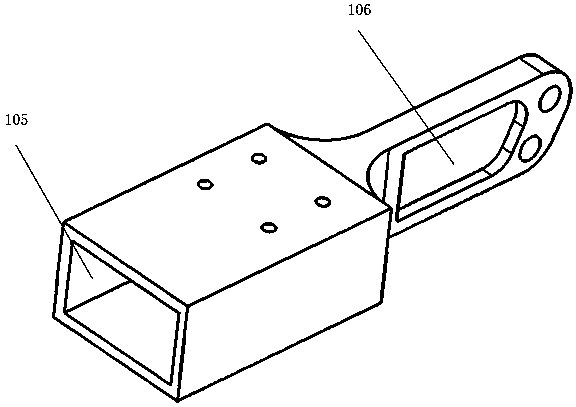
[0018] figure 2 and image 3 A schematic diagram of the mouth-shaped beam connector 3 of the present ...


PUM


Abstract

The invention relates to a mouth-shaped beam connecting device of a composite wing and a fuselage. The mouth-shaped beam connecting device comprises a mouth-shaped beam, a mouth-shaped beam connecting piece and a beam separating frame, wherein the mouth-shaped beam connecting piece is connected with an upper edge strip and a lower edge strip of the mouth-shaped beam by bolts and is connected with a left web and a right web of the mouth-shaped beam by adhesive; the beam separating frame consists of a separating frame and a connecting piece; the two ends of the connecting piece are respectively connected with the mouth-shaped beam connecting piece and the separating frame by bolts. A mouth-shaped beam connector of the mouth-shaped beam connecting device is made of aluminum alloy, so that processing is facilitated, and the connection reliability is improved; the mouth-shaped beam connector is connected with the webs by adhesive, so that the connection weight is lightened; the force transmission efficiency of root skin is fully exerted, but the requirement on the skin molding quality is high.

Description

technical field [0001] The invention relates to a mouth-shaped beam connection device for a wing and a fuselage. Background technique [0002] The connection between the wing and the fuselage is divided into peripheral connection scattered force transmission and concentrated force transmission according to the force transmission form. Due to their different performances, they can be used for aircraft with different purposes. Among them, the number of bolts for distributed force transmission in the peripheral connection is relatively large. The advantage is that the force transmission efficiency of the skin at the root of the wing is fully utilized, and no special complicated connection joints are required, which is conducive to reducing the weight of the structural design. The disadvantage is that the wing-body connection is increased. The assembly workload is heavy, and the matching tolerance between the bolt and the hole must be increased, which will adversely affect the t...

Claims


Application Information

Patent Timeline
Patent Type & Authority Applications(China)
IPC IPC(8): B64C1/00
Inventor 赫晓东胡平尹维龙王云杨张大为姜超
Owner HARBIN INST OF TECH
Features
  • R&D
  • Intellectual Property
  • Life Sciences
  • Materials
  • Tech Scout
  • Unparalleled Data Quality
  • Higher Quality Content
  • 60% Fewer Hallucinations
Learn More