

Ampoule sealing mechanism
An installation mechanism and sealing technology, which can be used in flange-type bottle caps, packaging and other directions, can solve problems such as unfavorable production efficiency of powder injection drugs, and achieve the effects of simple structure, reduced impact and improved installation efficiency.
- Summary
- Abstract
- Description
- Claims
- Application Information
AI Technical Summary
Problems solved by technology
Method used
Image

Examples
Embodiment 1
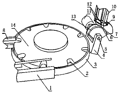
[0025] Such as Figure 1 to Figure 3 , an ampoule sealing mechanism provided by the present invention, comprising a bottle conveying mechanism and a bottle cap installation mechanism located on the side of the bottle conveying mechanism;
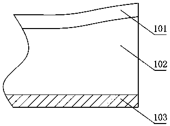
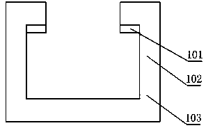
[0026] The bottle conveying mechanism includes a barrel-shaped material retaining barrel 3, in which a turntable 14 is arranged, the turntable 14 is connected with a drive motor, and the edge of the turntable 14 is provided with a plurality of ring-shaped evenly distributed The ampoule bayonet 2, the side of the turntable 14 is also provided with a bottle outlet groove 1 and a bottle inlet groove 8, the bottle outlet groove 1 is a groove structure with side walls 102 on both sides and a bottom edge 103 on the bottom, The inner wall surface of the side wall 102 of the bottle outlet 1 inlet end is also provided with an arc stopper 101, and the distance between the arc stopper 101 and the bottom edge 103 decreases linearly from the inlet end to...
Embodiment 2
[0030] This embodiment is further limited on the basis of embodiment 1: as Figure 1 to Figure 3 , in order to improve the working efficiency of the present invention, the tangent of the closest point on the side of the turntable 14 to the hinged rod 5 is parallel to the hinged rod 5, there are two suction ports 12, and the distance between the suction ports 12 is the same as any The distance between two adjacent ampoule bayonets 2 is equal.
[0031] In order to facilitate the adsorption of the bottle cap by the suction port 12 , the bottle cap installation mechanism also includes a material stopper 6 , and the material stopper 6 is fixed on the suction cap seat 7 and located below the suction port 12 .
Embodiment 3
[0033] This embodiment is further limited on the basis of embodiment 1: as Figure 1 to Figure 3 , the bottle cap feeding tank 10 is in the shape of a T-shaped tank. The bottle cap feeding trough 10 is set in a T-shaped groove shape. When in use, the wider side of the bottle cap is placed in the bottle cap feeding trough 10, so that the suction port 12 can only be adsorbed to the wider side of the bottle cap. One side, and the narrower side of the bottle cap itself is used to cooperate with the ampoule, that is, the above settings are also convenient for the installation of the bottle cap.
PUM
 Abstract
Description
Claims
Application Information