
Process reaction chamber and process equipment

A reaction chamber and process technology, applied in the field of microelectronics, can solve problems such as uneven heating temperature, lower process uniformity, and uneven radial distribution, and achieve uniform heating temperature, avoid uneven induction heating, and evenly distribute density Effect

Inactive Publication Date: 2014-07-02
BEIJING NAURA MICROELECTRONICS EQUIP CO LTD
View PDF2 Cites 1 Cited by
  • Summary
  • Abstract
  • Description
  • Claims
  • Application Information

AI Technical Summary

Problems solved by technology

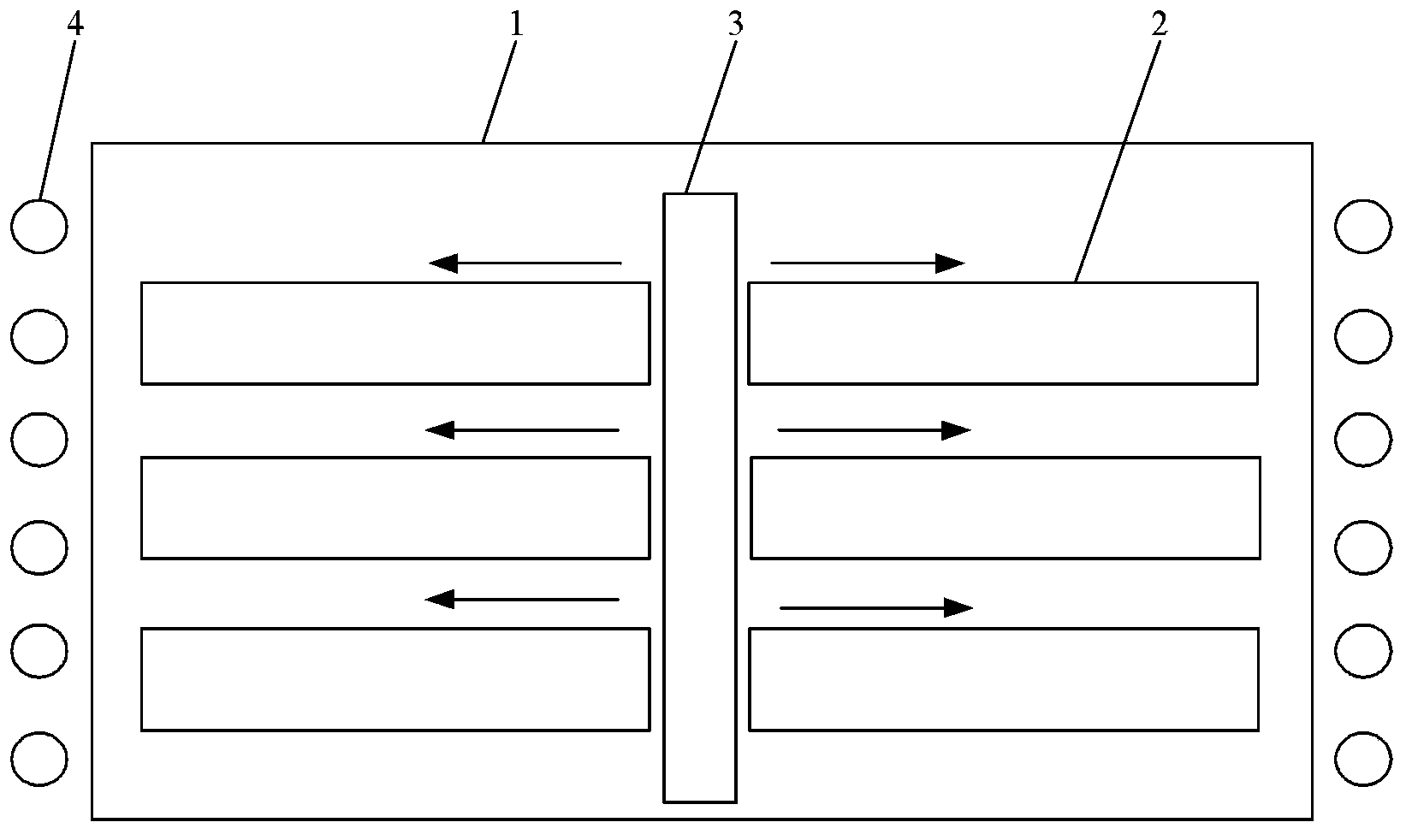
Therefore, the density of the magnetic force lines passing through the carrying device in the magnetic field is not uniform along the radial distribution of the carrying device 2, which leads to uneven heating temperature of the carrying device 2, thereby reducing the uniformity of the process

Method used


Image

  • Process reaction chamber and process equipment
  • Process reaction chamber and process equipment

Examples

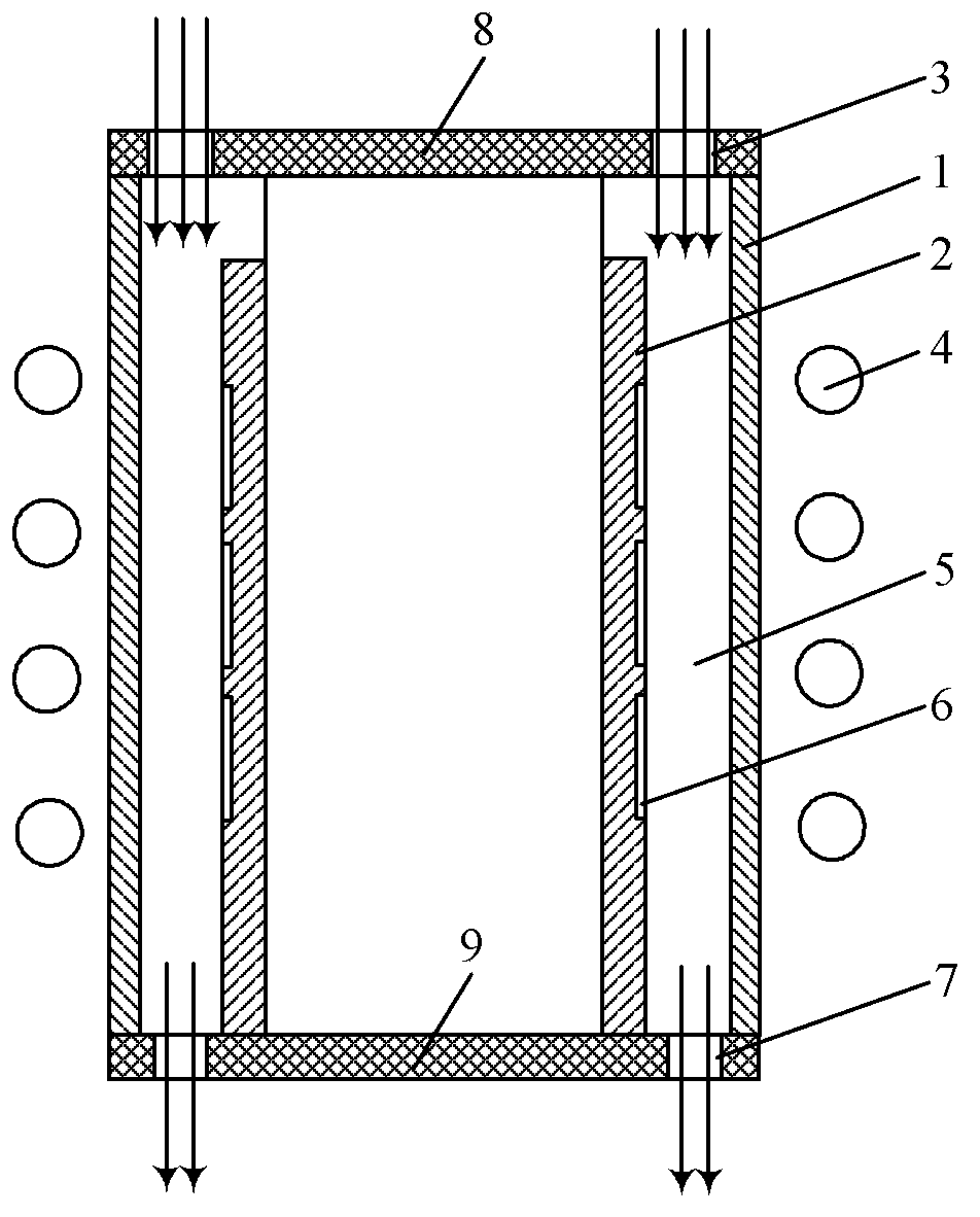

Embodiment Construction

[0022] In order to enable those skilled in the art to better understand the technical solution of the present invention, the following in conjunction with the attached

[0023] The figure describes in detail the process reaction chamber and process equipment provided by the present invention.

[0024] figure 2 A schematic structural diagram of a process reaction chamber provided in Embodiment 1 of the present invention, as shown in figure 2 As shown, the process reaction chamber includes: a chamber 1, a carrying device 2, an air inlet device 3 and an induction coil 4, the induction coil 4 is located outside the chamber 1, the induction coil 4 is used to generate a magnetic field, and the carrying device 2 is arranged in the chamber The inside of the body 1 is arranged coaxially with the cavity 1, a gas channel 5 is formed between the carrier device 2 and the cavity 1, a substrate 6 is placed on the outer peripheral surface of the carrier device 2, and the substrate 6 is loc...


PUM


Abstract

The invention discloses a process reaction chamber and process equipment. The process reaction chamber comprises a chamber body, a bearing device, a gas inlet device and induction coils, wherein the induction coils are located out of the chamber body and used for generating a magnetic field, the bearing device is arranged in the chamber body and is coaxial with the chamber body, a gas channel is formed between the bearing device and the chamber body, substrates are disposed on the outer peripheral surface of the bearing device and located in the gas channel, and the gas inlet device is used for introducing process gas into the gas channel. According to a technical scheme in the invention, density of magnetic lines passing through the bearing device is uniformly distributed, so the induction coils have a uniform heating temperature in heating of the bearing device, and thus, process uniformity is improved.

Description

technical field [0001] The invention relates to the technical field of microelectronics, in particular to a process reaction chamber and process equipment. Background technique [0002] Metal-organic chemical vapor deposition (Metal-organic Chemical VaporDeposition, hereinafter referred to as: MOCVD) technology is a new technology for the preparation of compound semiconductor thin slice single crystal proposed by Manasevit et al. . MOCVD technology is a new type of vapor phase epitaxy growth technology developed on the basis of vapor phase epitaxy (Vapor Phase Epitaxy, hereinafter referred to as: VPE). MOCVD technology is mostly used in the manufacture of LEDs, and the MOCVD reaction chamber is a device for manufacturing LEDs. The mainstream MOCVD reaction chambers on the market can include: horizontal reaction chambers or vertical reaction chambers. At present, the typical MOCVD reaction chamber is a horizontal reaction chamber. The distribution of the thermal field mod...

Claims


Application Information

Patent Timeline
IPC IPC(8): C23C16/44C23C16/46
Inventor 董志清
Owner BEIJING NAURA MICROELECTRONICS EQUIP CO LTD
Learn More