
Sealing equipment and construction technology of lng full-contained tank vault air blowing jacking process

A sealing device and air blowing technology, applied in mechanical equipment, engine sealing, fixed-capacity gas storage tanks, etc., can solve problems such as insufficient rubber plate support, cumbersome installation of steel gussets, material consumption and waste, and achieve easy installation Dismantling, sealing effect is remarkable, and the effect of reducing the amount of processing

Active Publication Date: 2016-03-23
SINOPEC TENTH CONSTR
View PDF5 Cites 0 Cited by
  • Summary
  • Abstract
  • Description
  • Claims
  • Application Information

AI Technical Summary

Problems solved by technology

This is a kind of soft seal. The disadvantages of this sealing method are: the rubber plate itself has insufficient support, the installation of the steel gusset is cumbersome, the friction between the tank wall and the tank wall is large during the jacking process, and material consumption is wasteful.

Method used


Image

  • Sealing equipment and construction technology of lng full-contained tank vault air blowing jacking process
  • Sealing equipment and construction technology of lng full-contained tank vault air blowing jacking process
  • Sealing equipment and construction technology of lng full-contained tank vault air blowing jacking process

Examples


Embodiment 1

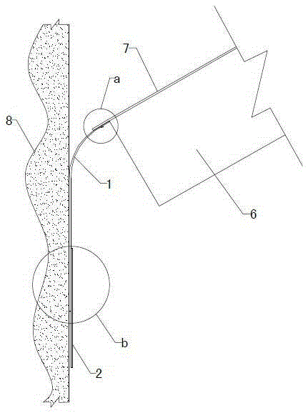
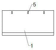
[0031] 1) Install the main sealing plate: multiple sheets of galvanized iron sheets with a specification of 1442mm×700mm are determined as the main sealing plate 1, and the lower edge of the main sealing plate 1 is bent inward by 12o with a bending width of 10mm. Set up fixing holes 5 on the upper edge of the main sealing plate 1, the distance between the fixing holes 5 is 447mm, use the gantry plate 3 and wedge 4 to fix the main sealing plate 1 on the lower surface of the tank top skin plate 7 at the position of the fixing holes 5 After the fixation is completed, spot weld the wedge 4 on the skin plate 7; then install the main sealing plate 1 one by one in sequence, and the overlap between the main sealing plates 1 is 110mm to ensure a tight connection between the two; then use the sealing Glue seals the gap between the main seal plate 1 connections.

[0032] 2) Install the auxiliary sealing plate: After the main sealing is completely installed, stick the auxiliary sealing so...

Embodiment 2

[0035] 1) Install the main sealing plate: multiple sheets of galvanized iron sheets with a specification of 1442mm×700mm are determined as the main sealing plate 1, and the lower edge of the main sealing plate 1 is bent inward by 12o with a bending width of 10mm. Set up fixing holes 5 on the upper edge of the main sealing plate 1, the distance between the fixing holes 5 is 447mm, use the gantry plate 3 and wedge 4 to fix the main sealing plate 1 on the lower surface of the tank top skin plate 7 at the position of the fixing holes 5 After the fixation is completed, spot-weld the wedges 4 on the skin plate 7; then install the main sealing plates 1 one by one in turn, and the overlap between the main sealing plates 1 is 100 mm to ensure a tight connection between the two; then use the sealing Glue seals the gap between the main seal plate 1 connections.

[0036] 2) Install the auxiliary sealing plate: After the main sealing is completely installed, stick the auxiliary sealing sof...

Embodiment 3

[0039] 1) Install the main sealing plate: multiple sheets of galvanized iron sheets with a specification of 1442mm×700mm are determined as the main sealing plate 1, and the lower edge of the main sealing plate 1 is bent inward by 12o with a bending width of 10mm. Set up fixing holes 5 on the upper edge of the main sealing plate 1, the distance between the fixing holes 5 is 447mm, use the gantry plate 3 and wedge 4 to fix the main sealing plate 1 on the lower surface of the tank top skin plate 7 at the position of the fixing holes 5 After the fixation is completed, spot weld the wedge 4 on the skin plate 7; then install the main sealing plate 1 one by one in sequence, and the overlap between the main sealing plates 1 is 110mm to ensure a tight connection between the two; then use the sealing Glue seals the gap between the main seal plate 1 connections.

[0040] 2) Install the auxiliary sealing plate: After the main sealing is completely installed, stick the auxiliary sealing so...


PUM


Abstract

The invention relates to a set of sealing equipment and construction technology in the LNG full containment tank vault air-blowing jacking process and belongs to the technical field of LNG full containment tank equipment. The equipment comprises a main seal and an auxiliary seal. The main seal comprises a plurality of main sealing plates (1) which are connected end to end in an overlapped mode, and the upper edges of the main sealing plates (1) are fixed to the lower surface of a tank top covering plate (7). The auxiliary seal comprises auxiliary sealing soft plates (2) connected to the lower portions of the main sealing plates (1) in an overlapped mode. According to the construction technology, after the main sealing plates (1) and the auxiliary sealing soft plates (2) are cut according to specific specifications, the main sealing plates (1) are fixed to the lower surface of the tank top covering plate (7) through a batter board (3) and wedges (4), the auxiliary sealing soft plates (2) are bonded to the lower edges of the main sealing plates (1), after sealing is qualified, enough air is introduced in, and then vault air-blowing jacking is completed. Through the sealing equipment and the construction technology in the LNG full containment tank vault air-blowing jacking process, the problems that a sealing system in the LNG full containment tank vault air-blowing jacking process is difficult to install, poor in sealing effect and high in requirement for a concrete outer tank wall are solved.

Description

technical field [0001] The invention relates to sealing equipment and construction technology for the air-blow jacking process of the arch top of an LNG full-containment tank, and belongs to the technical field of LNG full-containment tank equipment. Background technique [0002] The LNG full-containment tank is a large-scale storage device for liquefied gas. During the construction of the LNG full-containment tank, after the construction of the ceiling and vault is completed at the inner bottom of the concrete outer tank, the overall air-blown roof needs to be raised to the position of the tank top to fix it. The sealing process in the air blowing jacking process is very critical. Among them, the gap sealing between the tank top plate and the concrete outer tank is the most critical. In this regard, the traditional sealing process is mainly divided into two types: soft seal and hard seal. For example: 1. A galvanized iron sheet is installed as a whole around and under the...

Claims


Application Information

Patent Timeline
Patent Type & Authority Patents(China)
IPC IPC(8): F16J15/16F17C1/00
Inventor 翁大龙张继军张胜男潘吉龙宋纯民李峰
Owner SINOPEC TENTH CONSTR
Learn More