Moving-resistant level gage allowing connection line to be separated from shifting fork assembly

A technology of shifting fork assembly and material level gauge, which is applied to engine components, lubricating parts, engine lubrication, etc., can solve the problems that the shifting fork action axis and the system detection axis are not the same, the probability of failure is high, and the cost is high. The effect of reducing the randomness of the arm position, improving the reliability of electricity consumption and improving product quality

Active Publication Date: 2014-07-02
辽阳开发区仪表有限公司
View PDF8 Cites 3 Cited by
  • Summary
  • Abstract
  • Description
  • Claims
  • Application Information

AI Technical Summary

Problems solved by technology

[0004] However, after actual feedback, two serious shortcomings were found: one is that the switch is pressed on the shift fork, and the lead wire of the switch swings with the system, causing the lead wire to break; There is a large difference in motion sensitivity in both directions
However, four serious shortcomings were found: one is that the switch is pressed on the shift fork, and the lead wire of the switch swings with the system, causing the lead wire to break; the other is that most of the micro switches are used under the condition of AC220V, and there are problems with the lead wire and the switch. There are also hidden dangers in the safety of instrument use and personal safety; the third is that the shift fork action axis is not the same as the system detection axis, and the action axes of the two shift forks are also independent, and the action torque has a great relationship with the position of the rotating arm installed on the motor shaft , and the action elastic force of the micro switch itself generates a torque on the fork shaft, resulting in a large difference in the action sensitivity in the left and right directions of the swing detection
The ZL 2 0012543.0 shift fork invented in 2007 is a fixed structure, the action of the switch is blocked by the detection board, and the driving motor body is reversed to drive the micro switch. There is no opening and closing action, so there is no buffer) and the manufacture is more complicated
[0008] Therefore, the current material level gauge has a high probability of failure due to its complex structure and high cost, and its switch connection and shift fork components are likely to cause the material level gauge to fail

Method used


Image

  • Moving-resistant level gage allowing connection line to be separated from shifting fork assembly
  • Moving-resistant level gage allowing connection line to be separated from shifting fork assembly
  • Moving-resistant level gage allowing connection line to be separated from shifting fork assembly

Examples


Embodiment 1

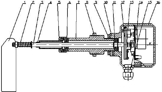
[0031] After the base 10 and the shaft cylinder 7 of the resistance-moving material level gauge of the present invention are screwed tightly, they are then locked with a lock nut 9 so that there is no relative movement between the two. Bearings 6, 11 are installed at both ends of the shaft cylinder 7, so that the detection shaft 3 and the shaft cylinder 7 can rotate freely. The detection shaft 3 is equipped with a shift fork assembly 12 at one end of the table seat, and the shift fork assembly 12 can rotate freely on the detection shaft 3 . Between the left shift fork 25 and the right shift fork 31, use the positioning piece 13 and use the tension spring to maintain the position between the two, and use the nut to insert the inner hole of the positioning piece 13 into the detection shaft 3, and there should be no firmness between them. relative movement. The other end of the detection shaft 3 is installed with a sealing rubber sleeve 4, put the knurled cap 5 on the sealing ru...


PUM


Abstract

The invention provides a moving-resistant level gage allowing a connection line to be separated from a shifting fork assembly, and relates to a solid material level gage. A motor (18) is connected with a base (10) which is connected with a beam barrel (7), and the beam barrel (7) is provided with a front bearing (6) and a rear bearing (11) and combined with a shaft (3); one end of the shaft (3) is provided with a detection board (1), the other end of a spring (2) is provided with the shifting fork assembly (12) and a locating sheet (13), and the shaft (3) is in clearance fit with the shifting fork assembly (12); a gage base (12) is connected with a gage cover (16), and a motor assembly (14) is provided with a microswitch (23), a terminal (19), a rotary arm (22) and idler wheels (21). The moving-resistant level gage structurally avoids accidents caused by breaking off of a side line, and is simple in structure and low in cost, and a level switch controlled automatically is particularly in common use of upper limit and lower limit alarm of feeding bins in the industries of chemical engineering, metallurgy, mines, road building, grain, environment protection and the like.

Description

technical field [0001] The invention relates to a solid-state material level gauge, in particular to a resistance-moving type material level gauge whose connection line is separated from a shift fork assembly. Background technique [0002] Resistance-moving level gauges are used in the level measurement of solid materials. There are various models with similar functions. However, the existing resistance-moving level gauges have a complex structure, which leads to a high probability of failure and high cost. For this reason the applicant has carried out continuous improvement respectively, and has applied for a Chinese patent successively, as: [0003] CN2053330U patent, the level gauge has adopted a piston reciprocating transmission system. A seal is used between the shaft and the casing to isolate the dust in the silo from the transmission system of the level gauge. It can operate reliably in the dusty environment of the silo and realize level control. There is also the ...

Claims


Application Information

Patent Timeline
Patent Type & Authority Applications(China)
IPC IPC(8): G01F23/00
Inventor 杜国凯张明杜名方
Owner 辽阳开发区仪表有限公司
Why Eureka
Try Eureka