Electric dimming device and car lamp online detecting system

A technology of a dimming device and a detection system, applied in the direction of testing optical performance, etc., can solve the problems of low dimming accuracy, affecting the compactness of the equipment, and increasing the size of the equipment, so as to improve the dimming speed and accuracy, enhance safety and The effect of stability and perfect automation

Inactive Publication Date: 2014-07-02
UNIV OF SHANGHAI FOR SCI & TECH
View PDF7 Cites 3 Cited by
  • Summary
  • Abstract
  • Description
  • Claims
  • Application Information

AI Technical Summary

Problems solved by technology

Therefore, there are the following problems: on the one hand, the accuracy of manual dimming is low, which seriously affects the light inspection results; on the other hand, it is impossible to realize the full automation of the entire inspection process, which seriously restricts the efficiency of lights
In addition, in order to facilitate manual operation, it is bound to impose certain restrictions on the overall structure of the testing equipment, which may increase the volume of the equipment or affect the overall compactness of the equipment and the fluency of the testing process, which is not suitable for strict requirements on the size of the testing equipment. occasion
[0004] Nowadays, all fields of industrial production are committed to replacing manpower with machinery. Efficient workflow and simple mechanical structure have become the goals pursued by enterprises. CAN bus is widely used for its ease of use, stable communication and flexible configuration. Automotive industry, on-line detection and many other fields, but the technology of applying CAN bus to the on-line detection system of car lights to realize dimming function is still rare. Therefore, a CAN bus-based structure can replace manual operation to realize automatic dimming The electric dimming device and the online detection system of the car lights are particularly important

Method used


Image

  • Electric dimming device and car lamp online detecting system
  • Electric dimming device and car lamp online detecting system
  • Electric dimming device and car lamp online detecting system

Examples


Embodiment Construction

[0020] In order to make the technical means, creative features, goals and effects of the present invention easy to understand, the following embodiments will specifically illustrate the electric dimming device and the online detection system for vehicle lights of the present invention in conjunction with the accompanying drawings.

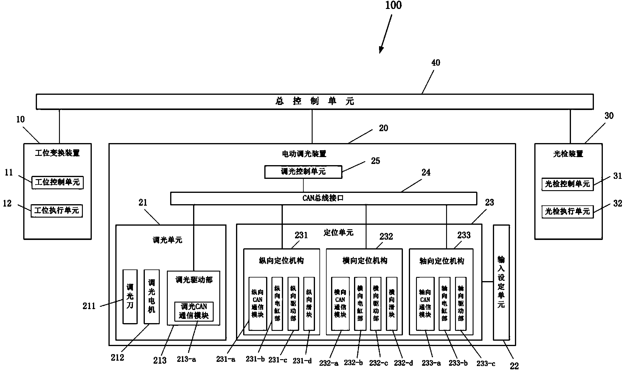
[0021] figure 1 It is a structural block diagram of the vehicle light on-line detection system in the embodiment of the present invention.

[0022] Such as figure 1 As shown, in this embodiment, the vehicle lamp online detection system 100 detects the light distribution characteristics of the cut-off line of the vehicle lamp to be detected which is set at a predetermined angular position at different positions, and the predetermined angular position is the detection position , the adjustment of the light-dark cut-off line position of the vehicle lamp to be detected needs to be realized by rotating the dimming screw on the outside of the vehicle la...


PUM


Abstract

The invention provides an electric diming device. A diming screw arranged in a to-be-detected car lamp arranged at a preset angle position is rotated to adjust the position of a light and shadow dividing line of the to-be-detected car lamp. The electric dimming device is included in a car lamp online detecting system, and receives car lamp in-place signals, dimming starting signals for starting to rotate the dimming screw, forward dimming signals for rotating the dimming screw in the forward direction, reverse dimming signals for rotating the dimming screw reversely and dimming stopping signals for stopping rotating the dimming screw, wherein the car lamp in-place signals are sent when a work position conversion device in the car lamp online detecting system conveys the to-be-detected car lamp to the preset angle position, and the dimming starting signals are sent by a light detecting device in the car lamp online detecting system. The electric diming device is characterized in that a dimming unit, an input setting unit, a locating unit, a CAN bus interface and a dimming control unit, wherein the dimming unit comprises a dimming cutter, a dimming motor and a dimming driving portion, and the locating unit comprises a longitudinal locating mechanism, a transverse locating mechanism and an axial locating mechanism.

Description

technical field [0001] The invention relates to an electric dimming device capable of automatic dimming and an on-line detection system for vehicle lamps. Background technique [0002] Along with the raising of economic level, automobile has become the main means of transportation in people's daily life. In order to ensure traffic safety while driving, the light beams emitted by the headlights or fog lights of the car should be as soft as possible, so as to avoid dazzling and other discomfort to the drivers and passengers of other vehicles in front. Therefore, the light and dark cut-off line of car lights The location is important. The national standard GB4599-2007 "Filament Bulb Headlamps for Automobiles" and the national standard GB4660-2007 "Filament Bulb Front Fog Lamps for Automobiles" respectively make specific regulations on the technical indicators of automotive headlights and fog lamps, pointing out the light and dark cut-off line The position can be adjusted with...

Claims


Application Information

Patent Timeline
IPC IPC(8): G01M11/02
Inventor 谢腾穆平安戴曙光金晅宏
Owner UNIV OF SHANGHAI FOR SCI & TECH
Why Eureka
Try Eureka