Electromagnetic compatibility test system

An electromagnetic compatibility and test system technology, applied in the direction of measuring electricity, measuring devices, measuring electrical variables, etc., can solve the problems of increasing instrument cost and uncertainty of test results, increasing amplifier gain requirements, and affecting test accuracy. To achieve the effect of shortening the length of the coaxial line, reducing the cost of equipment, and avoiding the impact

Inactive Publication Date: 2014-07-02
HONG FU JIN PRECISION IND (SHENZHEN) CO LTD +1
View PDF0 Cites 15 Cited by
  • Summary
  • Abstract
  • Description
  • Claims
  • Application Information

AI Technical Summary

Problems solved by technology

However, because the amplifier and receiver are located outside the anechoic chamber, the longer coaxial line leads to increased attenuation of the signal during transmission and higher requirements for the gain of the amplifier, which increases the cost of the instrument and the uncertainty of the test results
In addition, amplifiers and receivers are located outside the anechoic chamber, making it easy for noise to couple into the test system through the interface between instruments and affect the accuracy of the test

Method used


Image

  • Electromagnetic compatibility test system
  • Electromagnetic compatibility test system

Examples


Embodiment Construction

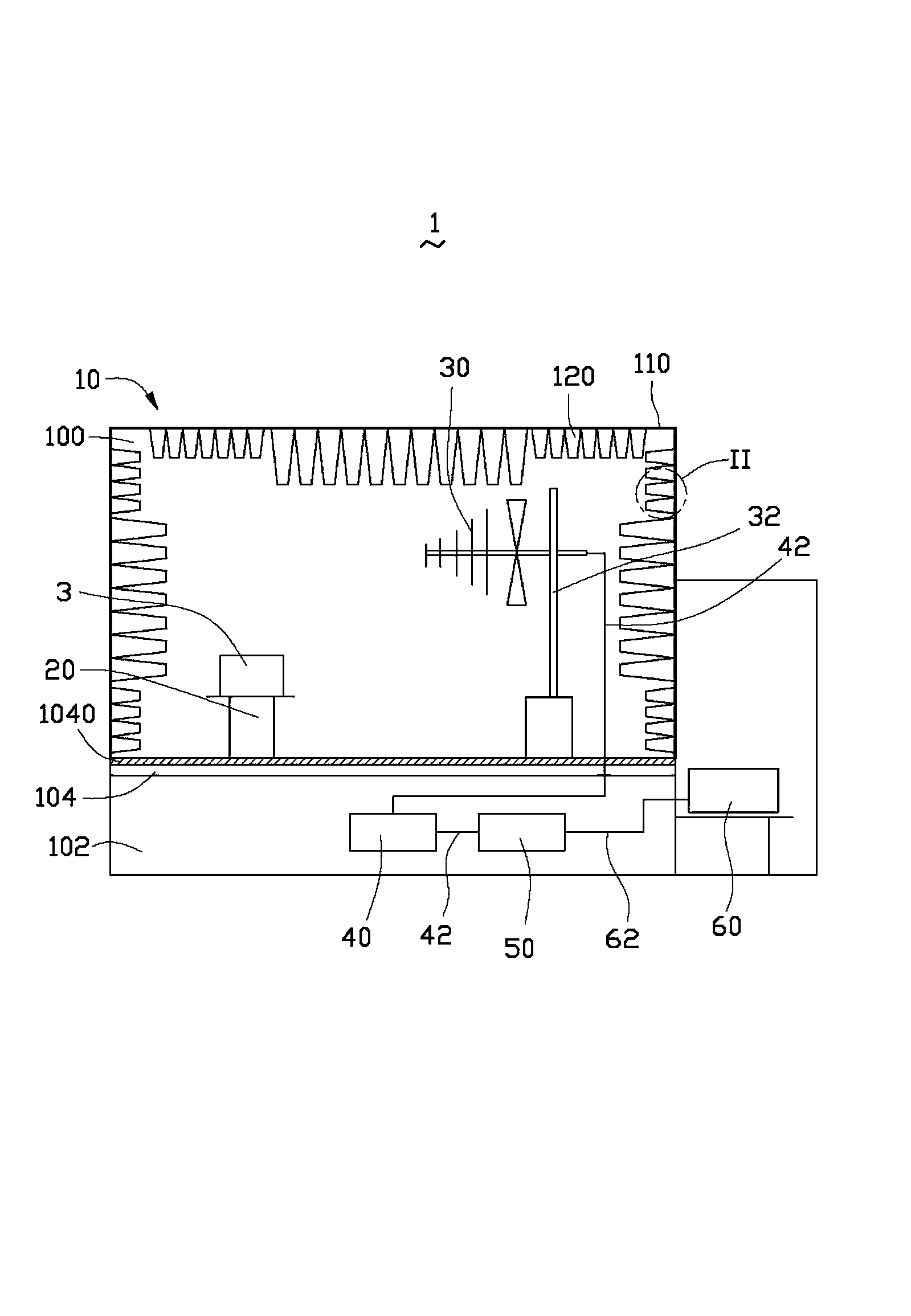
[0011] Such as figure 1 As shown, the embodiment of the present invention provides an electromagnetic compatibility testing system 1 , which includes an anechoic chamber 10 , a test bench 20 , an antenna 30 , an amplifier 40 , a receiver 50 and a computer 60 . The test bench 20 , antenna 30 , amplifier 40 and receiver 50 are all set in the anechoic chamber 10 . The test bench 20 is used to carry the test product 3 . The antenna 30 is used to receive the electromagnetic signal emitted by the test product 3 . The antenna 30 is connected to the amplifier 40 through a coaxial cable 42 to transmit electromagnetic signals. The amplifier 40 is connected to the receiver 50 through a coaxial cable 42 to transmit the amplified electromagnetic signal to the receiver 50 for reading.

[0012] The anechoic chamber 10 includes a testing chamber 100 and a shielding chamber 102 . A shielding spacer 104 is provided between the test chamber 100 and the shielding chamber 102 . A grounded shi...


PUM


Abstract

An electromagnetic compatibility testing system includes an anechoic chamber. The anechoic chamber includes a testing table, an antenna, an amplifier, and a receiver. A test sample is placed on the testing table. The antenna receives electromagnetic signals emitted by the test sample and transmits the electromagnetic signals to the amplifier via a coaxial cable. The receiver is connected to the amplifier via the coaxial cable analyzing the electromagnetic signals amplified by the amplifier.

Description

technical field [0001] The invention relates to an electromagnetic compatibility testing system. Background technique [0002] The existing electromagnetic compatibility testing system generally includes an anechoic chamber, an antenna arranged inside the anechoic chamber, an amplifier and a receiver arranged outside the anechoic chamber. The antenna receives the electromagnetic signal sent by the test product, and then transmits it to the amplifier outside the anechoic chamber through the coaxial cable for amplification, and then transmits the amplified signal to the receiver for reading through the coaxial cable. However, because the amplifier and receiver are located outside the anechoic chamber, the longer coaxial line leads to increased attenuation of the signal during transmission and higher requirements for the gain of the amplifier, which increases the cost of the instrument and the uncertainty of the test results. In addition, the amplifier and the receiver are loc...

Claims


Application Information

Patent Timeline
Patent Type & Authority Applications(China)
IPC IPC(8): G01R31/00
CPCG01R27/32G01R29/0814G01R29/0871
Inventor 何等乾
Owner HONG FU JIN PRECISION IND (SHENZHEN) CO LTD
Why Eureka
Try Eureka