Light guide plate

A light guide plate and light technology, which is applied in the field of light guide plates, can solve the problems of insufficient luminance, the number and increase of complex backlight system components, etc., achieve the best luminance and uniformity, and improve the effect of luminance

Inactive Publication Date: 2014-07-02
HONG FU JIN PRECISION IND (SHENZHEN) CO LTD +1
View PDF6 Cites 1 Cited by
  • Summary
  • Abstract
  • Description
  • Claims
  • Application Information

AI Technical Summary

Problems solved by technology

[0003] Since the light guide plate scatters the light as much as possible, the light transmitted through the light guide plate is scattered in various directions, which inevitably produces the defect of insufficient luminance due to the scattered light.
[0004] Usually, in order to overcome the defect of insufficient luminance, the light-emitting surface of the light guide plate is also provided with a prism plate. The refraction of the prism plate can converge the light directly in front of the light guide plate to improve the brightness of the light guide plate. However, this kind of prism plate The setting of the prism increases the number of components of the backlight system with a relatively complex structure, which is not conducive to the lightweight and thin design of the backlight system. Moreover, the light convergence effect of the prism may also cause the uniformity of the light guide plate to be unable to maintain, affecting the backlight system. quality

Method used


Image

  • Light guide plate
  • Light guide plate
  • Light guide plate

Examples


Embodiment Construction

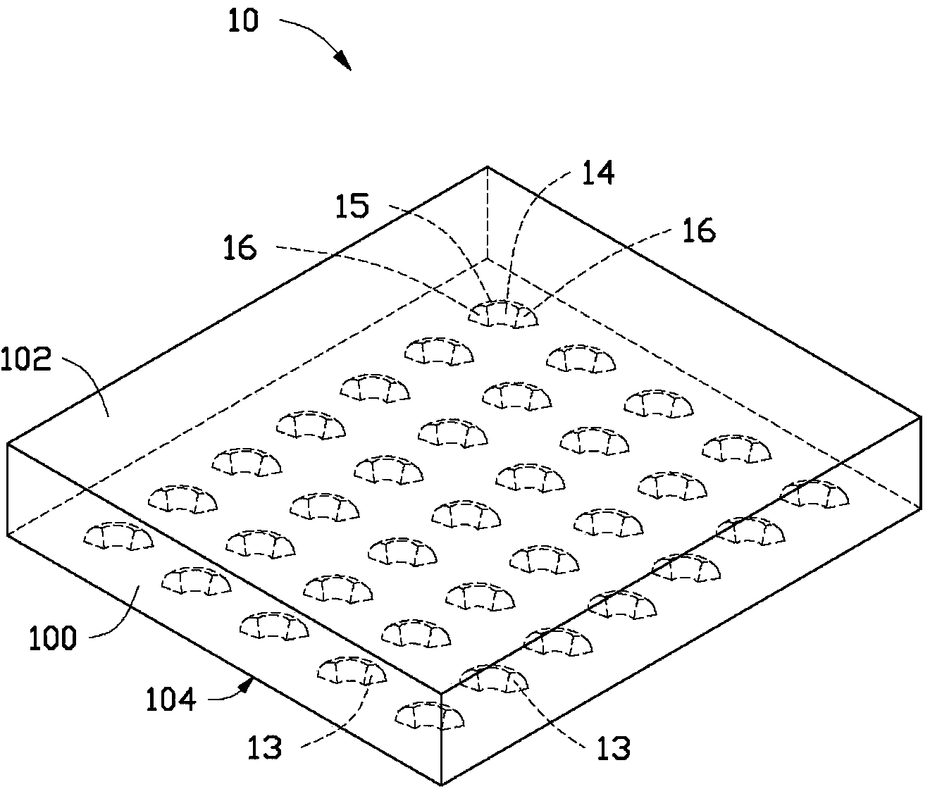
[0014] see figure 1 and figure 2 , a light guide plate 10 provided in an embodiment of the present invention includes a plurality of dots disposed thereon.

[0015] The light guide plate 10 is made of light-transmitting material, and includes a light-incident surface 100 , a light-exit surface 102 , and a bottom surface 104 opposite to the light-exit surface 102 .

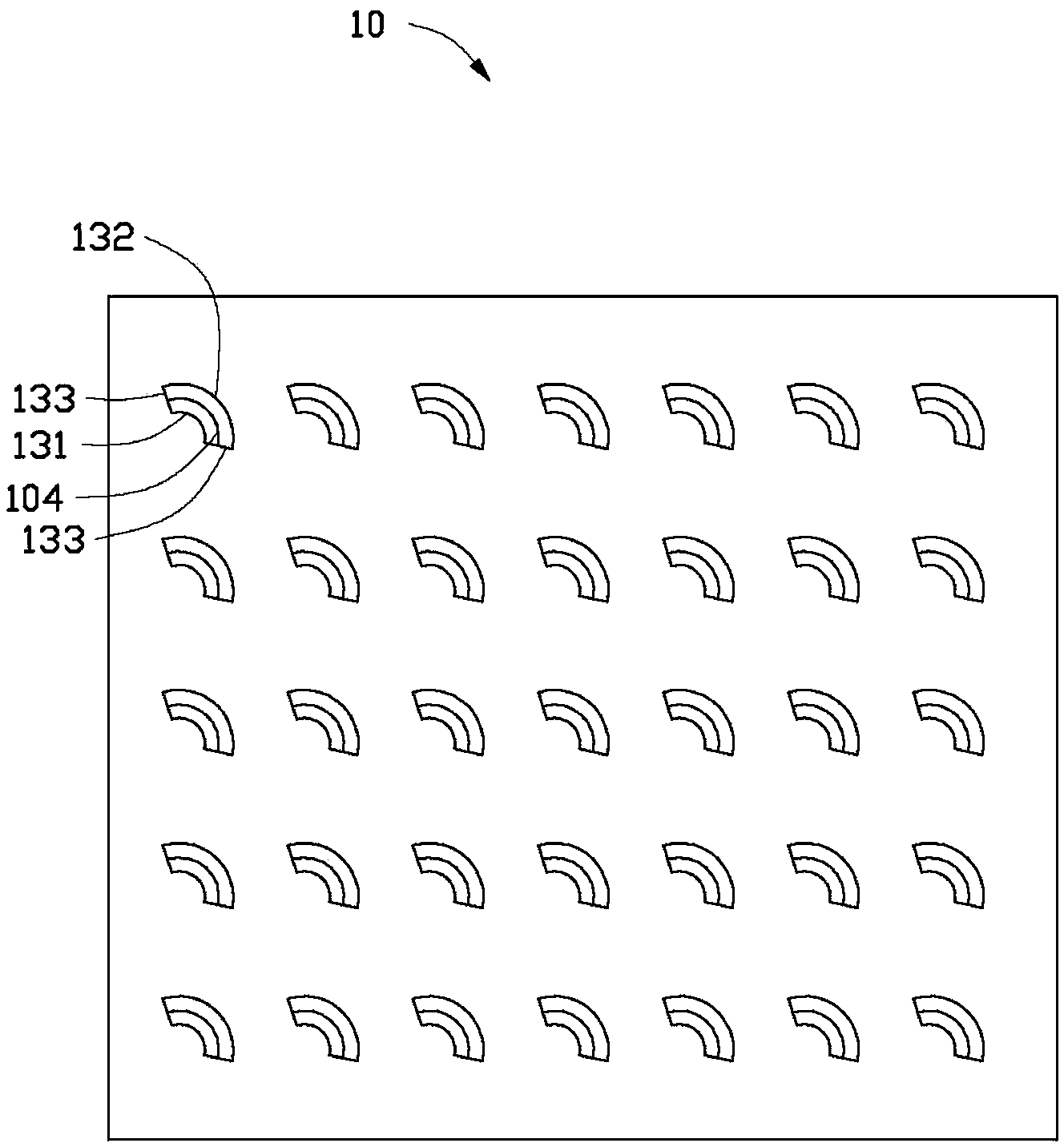
[0016] The dots are disposed on the bottom surface 104 for reflecting incident light thereon. In this embodiment, the dots are a plurality of depressions 13 formed on the bottom surface 104 .

[0017] The opening formed by each depression 13 on the bottom surface 104 is fan-shaped, and the fan ring includes an inner arc 131 with a smaller radius, an outer arc 132 with a radius larger than the inner arc 131, and an outer arc 132 connecting the inner arc 131 and the outer arc 132. The two straight lines 133.

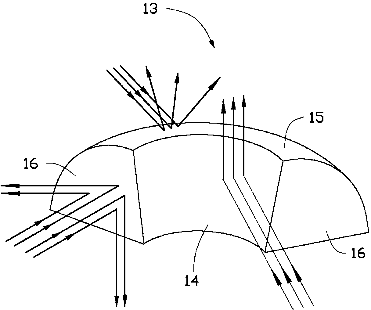
[0018] The four sidewalls of the recess 13 are a first curved surface 14 , a second curved surface 15 a...


PUM


Abstract

The invention relates to a light guide plate. The light guide plate comprises a light incidence surface, a light emergence surface, a bottom surface arranged opposite to the light emergence surface and net points arranged on the bottom surface, the net points comprise a first curved surface and a second curved surface, and two flat surfaces located on the first curved surface and the second curved surface, the first curved surface reflects light incident thereto to the light emergence surface with an angle vertical to the light emergence surface, the second curved surface radiates light incident thereto back to the inside of the light guide plate, and the two flat surfaces reflect and radiate light incident thereto to two sides of an initial incidence path of the light incident to the flat surfaces. The light guide plate has the advantages of both having relatively good luminance and uniformity.

Description

technical field [0001] The invention relates to a light guide plate for a backlight system, in particular to a light guide plate with dot distribution. Background technique [0002] Since the liquid crystal itself of the liquid crystal display panel does not have light-emitting characteristics, in order to achieve the display effect, it is necessary to provide a surface light source device for the liquid crystal display panel, such as a backlight system, whose function is to supply a surface light source with sufficient brightness and uniform distribution to the liquid crystal display panel. The backlight system in the prior art is mainly composed of a light source and a light guide plate. The light source can be arranged on one side or two opposite sides of the light guide plate and emit light to the light guide plate. The function of the light guide plate is to guide the transmission direction of the light so that the light is evenly emitted from the light emitting surfac...

Claims


Application Information

Patent Timeline
Patent Type & Authority Applications(China)
IPC IPC(8): G02B6/00F21V8/00
Inventor 王何立颖
Owner HONG FU JIN PRECISION IND (SHENZHEN) CO LTD
Why Eureka
Try Eureka