Method for designing circular array constant beamwidth beam former

A circular array and constant beam width technology, applied in the direction of instruments, sound-generating devices, etc., can solve the problems of complex operation and inaccuracy

Active Publication Date: 2014-07-02
NORTHWESTERN POLYTECHNICAL UNIV
View PDF3 Cites 9 Cited by
  • Summary
  • Abstract
  • Description
  • Claims
  • Application Information

AI Technical Summary

Problems solved by technology

[0005] In order to avoid the deficiencies of the prior art, the present invention proposes a circular ring array constant beam width beamformer design method, which solves the deficiencies of complex operation and inaccuracy in the prior art

Method used


Image

  • Method for designing circular array constant beamwidth beam former
  • Method for designing circular array constant beamwidth beam former
  • Method for designing circular array constant beamwidth beam former

Examples


specific Embodiment

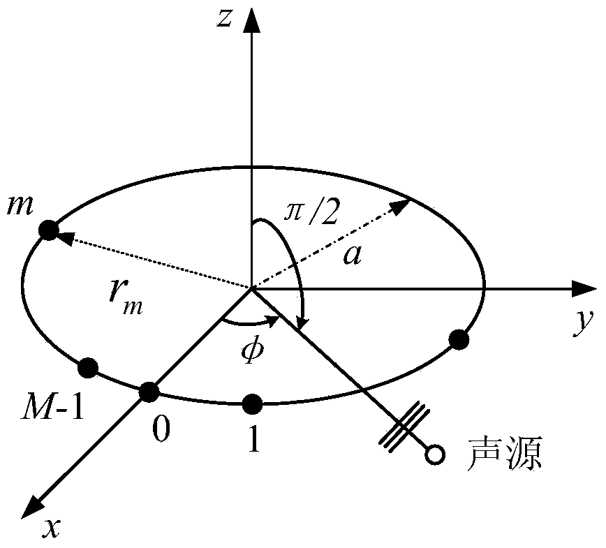
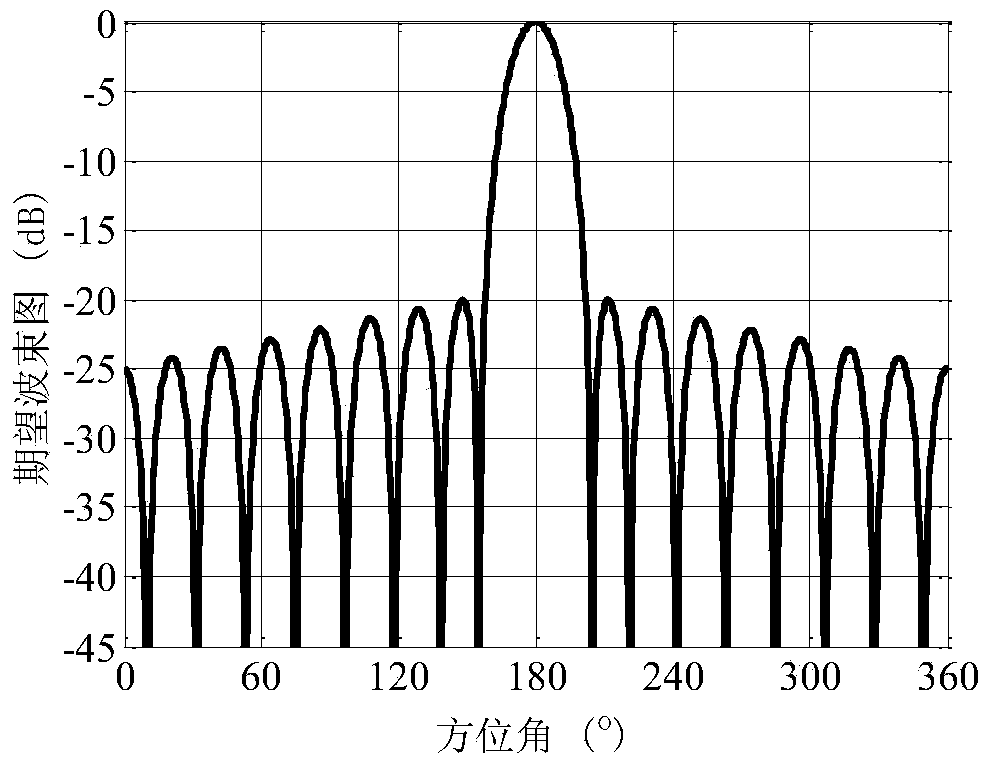
[0062] (1) Refer to figure 1 and 2 . The circular array includes M uniformly distributed array elements. Since the annular array pays more attention to the performance of beamforming in the horizontal plane, the expected beam is only a two-dimensional beam in the horizontal range. The desired beam is theoretically calculated by the circular ring array at the reference frequency, and its expression is:

[0063] B d ( k r a r , φ ) = Σ m = 0 M - 1 ω m * ( k r a r ) E ...


PUM


Abstract

The invention relates to a method for designing a circular array constant beamwidth beam former. The method for designing the circular array constant beamwidth beam former is simple and precise and is provided according to an even circular array. The characteristic of a circulant matrix is utilized in the method, an exact solution to a circular array minimum square error beam pattern synthesis problem is provided, and a finally-composited beam and a minimum square error are simply represented as the sum of subcomponent superposition. When the beam is expected to be transformed into a proper form, a closed expression of a weight vector of the constant beamwidth beam former can be obtained. The method overcomes the defects of the complex and imprecise operation in the prior art, an optimal solution is precisely represented as the sum of subcomponent composited, and the closed expression exists.

Description

technical field [0001] The invention belongs to a design method of a beamformer, and relates to a design method of a ring-shaped array constant beamwidth beamformer, which is suitable for wide-band target detection and wide-band target orientation estimation of a ring-shaped array, and belongs to underwater acoustics and array signal processing and sonar technology. Background technique [0002] Due to the simple formation, no starboard and starboard ambiguity, and the ability to form a substantially constant beam in the entire circumference, the circular array is widely used in the fields of sonar, radar, communication, and voice engineering. There are also endless signal processing methods for this array, among which the broadband beamforming method has received great attention. [0003] Because the beam output by conventional arrays varies with frequency, especially when the signal is incident from other directions of the main lobe, the spectrum of different frequency si...

Claims


Application Information

Patent Timeline
Patent Type & Authority Applications(China)
IPC IPC(8): G10K11/34
Inventor 杨益新汪勇马远良何正耀
Owner NORTHWESTERN POLYTECHNICAL UNIV
Why Eureka
Try Eureka