
An igbt module gate drive resistance equivalent adjustment circuit

A gate drive and regulation circuit technology, applied in the direction of electrical components, electronic switches, pulse technology, etc., can solve the problems that affect the working effect of IGBT module U4 and cannot adjust the resistance of gate drive resistor R5, etc., to achieve intelligent adjustment, The effect of safe working status and optimized working status

Active Publication Date: 2017-12-12
BYD SEMICON CO LTD
View PDF6 Cites 0 Cited by
  • Summary
  • Abstract
  • Description
  • Claims
  • Application Information

AI Technical Summary

Problems solved by technology

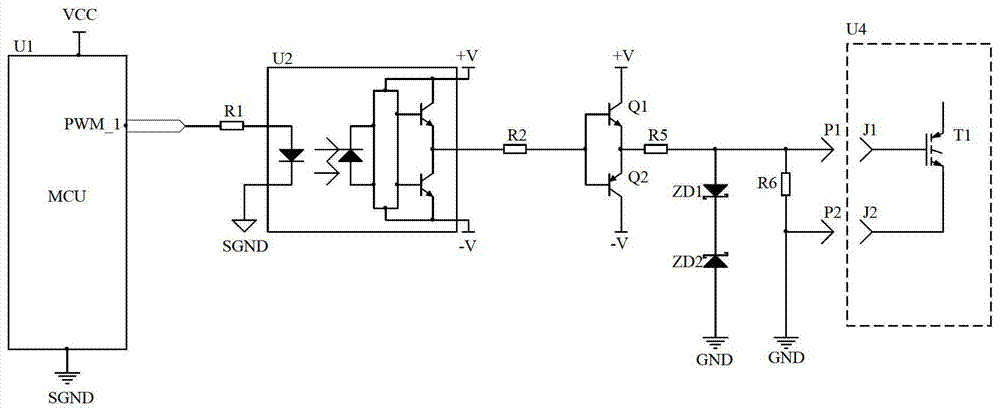
like figure 1 As shown, the gate drive resistor R5 in the prior art is fixed in the circuit by manual welding, its resistance value is fixed, and the resistance value of the gate drive resistor R5 cannot be adjusted according to the power of the IGBT module U4, and then Affect the working effect of IGBT module U4

Method used


Image

  • An igbt module gate drive resistance equivalent adjustment circuit
  • An igbt module gate drive resistance equivalent adjustment circuit
  • An igbt module gate drive resistance equivalent adjustment circuit

Examples


Embodiment Construction

[0022] Embodiments of the present invention are described in detail below, examples of which are shown in the drawings, wherein the same or similar reference numerals designate the same or similar elements or elements having the same or similar functions throughout. The embodiments described below by referring to the figures are exemplary only for explaining the present invention and should not be construed as limiting the present invention.

[0023] In the description of the present invention, unless otherwise specified and limited, it should be noted that the terms "installation", "connection" and "connection" should be understood in a broad sense, for example, it can be mechanical connection or electrical connection, or two The internal communication of each element may be directly connected or indirectly connected through an intermediary. Those skilled in the art can understand the specific meanings of the above terms according to specific situations.

[0024] The inventio...


PUM


Abstract

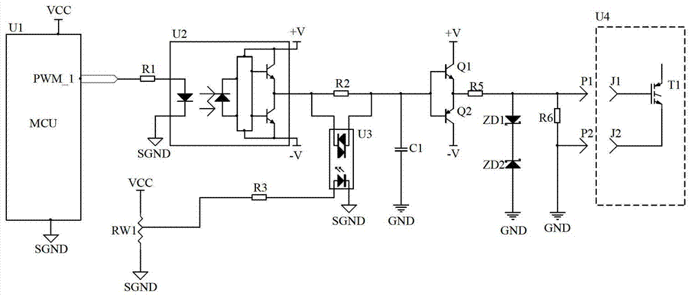
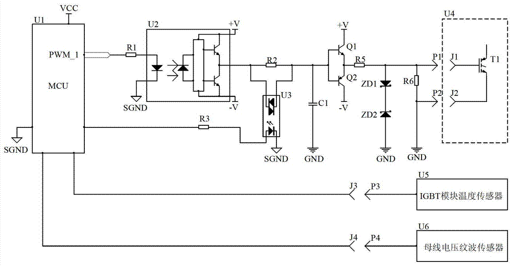
The present invention proposes an equivalent adjustment circuit for gate drive resistance of an IGBT module, comprising an IGBT module, an MCU, a first optocoupler and a drive module, a first resistor is connected between the MCU and the first optocoupler, and the drive module and the IGBT module A gate drive resistor is connected between them, and there is an integral circuit between the first optocoupler and the drive module. The integral circuit includes the equivalent resistance of the integral circuit and the first capacitor. By changing the resistance value of the equivalent resistance of the integral circuit, the integral circuit can be adjusted The time constant of the gate drive resistor can be adjusted equivalently. The equivalent adjustment circuit of the gate drive resistance of the IGBT module of the present invention can adjust the equivalent resistance of the gate drive resistance, and can drive IGBT modules with different powers without manually changing the gate drive resistance, thereby optimizing the working state of the IGBT modules.

Description

technical field [0001] The invention relates to the technical field of circuit design, in particular to an IGBT module gate drive resistance equivalent adjustment circuit. Background technique [0002] IGBT (Insulated Gate Bipolar Transistor, Insulated Gate Bipolar Transistor) is a composite power electronic device that came out in the mid-1980s. In terms of structure, it is equivalent to a MOSFET (Metal OxideSemiconductor Field Effect Transistor, metal-oxide- BJT (Bipolar Junction Transistor, Bipolar Junction Transistor) with thick base driven by Semiconductor Field Effect Transistor). The characteristics of high current density, on-state voltage drop, and high withstand voltage are widely used in power electronic equipment. [0003] At present, commonly used IGBT modules are driven by circuits such as EXB841, A316J, M57962, etc. These circuits are driven by optocoupler isolation, such as figure 1 As shown in the figure, U1 in the figure is MCU (Micro Control Unit, micro ...

Claims


Application Information

Patent Timeline
Patent Type & Authority Patents(China)
IPC IPC(8): H03K17/567
CPCH03K17/567H03K17/14H03K17/168H03K17/785
Inventor 蓝诚宇杨钦耀陈刚
Owner BYD SEMICON CO LTD
Learn More