
Dynamic expansion method of optical time domain reflectometer

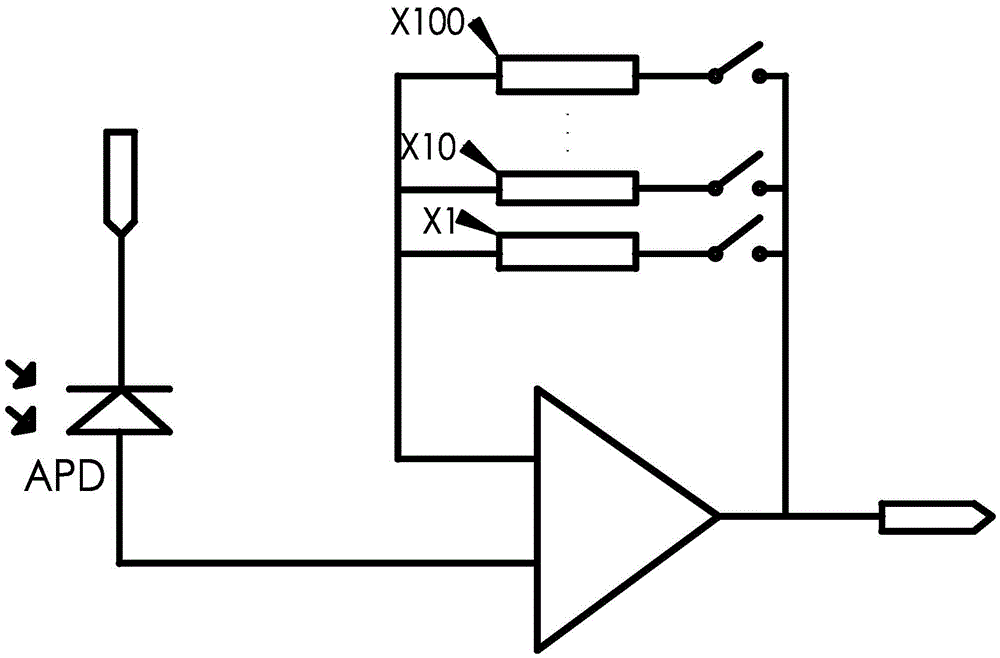
An optical time domain reflectometer and dynamic expansion technology, applied in electromagnetic wave transmission systems, electrical components, transmission systems, etc., can solve problems such as the inability to meet long-distance measurement design requirements, reduce the risk of radiation damage, and reduce heat generation. Problem, effect of low price

Active Publication Date: 2016-06-01
ZHEJIANG TIANCHAUNG XINCE COMM TECH
View PDF6 Cites 0 Cited by
  • Summary
  • Abstract
  • Description
  • Claims
  • Application Information

AI Technical Summary

Problems solved by technology

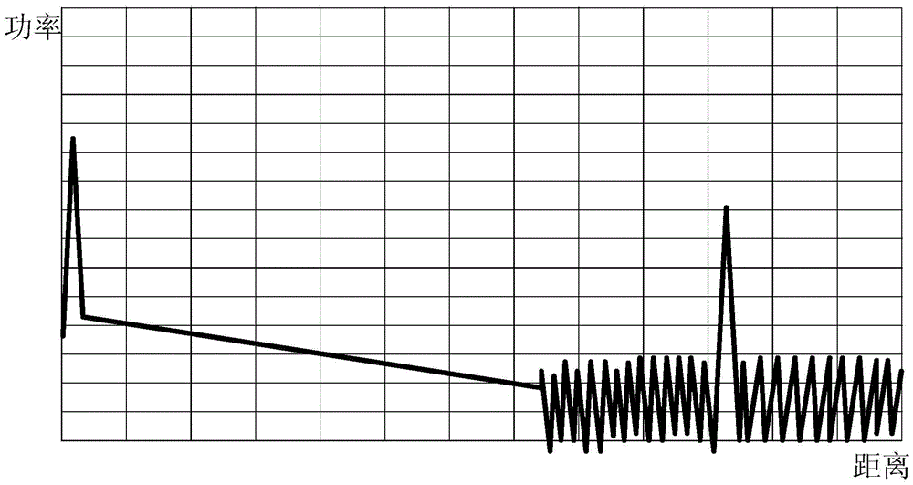
Although severe saturation does not occur, if image 3 The design requirements for long-distance measurement cannot be met

Method used


Image

  • Dynamic expansion method of optical time domain reflectometer
  • Dynamic expansion method of optical time domain reflectometer
  • Dynamic expansion method of optical time domain reflectometer

Examples


Embodiment Construction

[0023] The present invention will be further described below in conjunction with accompanying drawing.

[0024] see Figure 4 , the dynamic expansion method of the optical time domain reflectometer of the present invention is to connect the cathode terminal of the avalanche photodiode 1 with the bias voltage 2, and connect the anode terminal of the avalanche photodiode 1 with the first stage amplifier 3; the first stage amplifier 3 passes The transimpedance resistor 4 converts the current from the avalanche photodiode 1 into a voltage and then connects with the second stage amplifier 5, and at the same time connects the voltage as a small voltage signal 6 to the signal mixer 8; the second stage amplifier 5 will come from the first stage amplifier The voltage signal of 3 is amplified again and sent to the signal mixer 8 as the large voltage signal 7; the signal mixer 8 combines the input small voltage signal 6 and the large voltage signal 7 through calculation, and controls it ...


PUM


Abstract

The invention discloses a dynamic extension method of an optical time domain reflectometer. The cathode end of an avalanche photodiode is connected with a bias voltage, and the anode end of the avalanche photodiode is connected with a first-stage amplifier; the first-stage amplifier converts a current coming from the avalanche photodiode into a voltage through a transimpedance resistor, the voltage is then connected with the a second-stage amplifier, and meanwhile the voltage serves as a small-voltage signal to be connected to a signal mixer; the second-stage amplifier amplifies the voltage signal coming from the first-stage amplifier again, and the amplified voltage signal serves as a large-voltage signal to be transmitted into the signal mixer; the input small-voltage signal and the input large-voltage signal are combined through calculation by the signal mixer, and meanwhile the input small-voltage signal and the input large-voltage signal are controlled through the signal control end and output through the signal output end. By means of the dynamic extension method, cost is reduced, the power requirement for laser semiconductor diodes is reduced, the heating amount of the laser semiconductor diodes is reduced, and meanwhile risks of radiation injuries are reduced; disturbance influences of a power source on the overall performance are greatly reduced.

Description

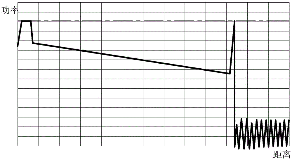
technical field [0001] The invention relates to a dynamic extension method, in particular to an optical time domain reflectometer dynamic extension method. Background technique [0002] At present, optical time domain reflectometers include large and small dynamic optical time domain reflectometers (OTDR) such as figure 1 As shown, but there are shortcomings that are difficult to overcome. [0003] Large dynamic OTDR generally measures the distance of more than 120Km, and the dynamic range exceeds 35dB. The high-power laser semiconductor used by the large dynamic OTDR is a semiconductor laser with an instantaneous optical power output exceeding 100mW. If an OTDR designed with a high-power laser is used, the Rayleigh scattering (Rayleigh) signal returned when measuring a short-distance fiber is strong, as figure 2 shown results in APD and amplifier saturation. Existing large dynamic OTDR technologies mainly use high-power lasers. Even if the method of reducing the signa...

Claims


Application Information

Patent Timeline
Patent Type & Authority Patents(China)
IPC IPC(8): H04B10/071
Inventor 夏震宇翟朝文刘平沈阳
Owner ZHEJIANG TIANCHAUNG XINCE COMM TECH
Learn More