
Electric power-steering device

A power steering device, an electric technology, which is applied to electric steering mechanisms, power steering mechanisms, steering mechanisms, etc., can solve the problem of the deterioration of the detection accuracy of the torque measuring instrument 8a, the dislocation of the partition plate 25, and the performance degradation of the electric power steering device. and other problems, to achieve the effect that the measurement accuracy will not deteriorate and the meshing state will not deteriorate.

Inactive Publication Date: 2014-07-02
NSK LTD
View PDF10 Cites 7 Cited by
  • Summary
  • Abstract
  • Description
  • Claims
  • Application Information

AI Technical Summary

Problems solved by technology

[0008] In contrast, in Figure 22 In the case of the structure shown, although there is no problem of complicated assembly work as described above, it is difficult to maintain the positioning accuracy of the output shaft 13a for a long time.
That is, the elastic member 26 disposed between the outer peripheral surface of the partition plate 25 and the inner peripheral surface of the gear box 20a will age with long-term use, and once its elasticity decreases, the partition plate 25 may be displaced.
When the partition plate 25 is misaligned, the resistance of the meshing portion between the worm of the worm gear reducer 7a and the worm wheel increases, and the detection accuracy of the torque measuring instrument 8a deteriorates.
Any of the above conditions will result in a reduction in the performance of the electric power steering

Method used


Image

  • Electric power-steering device
  • Electric power-steering device
  • Electric power-steering device

Examples


Embodiment Construction

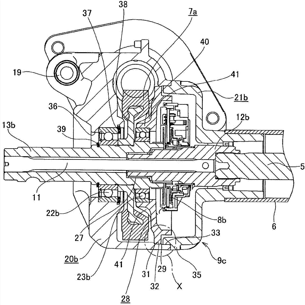
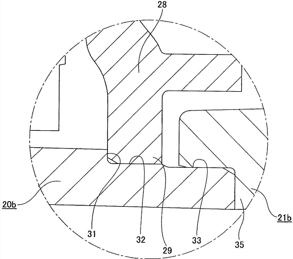
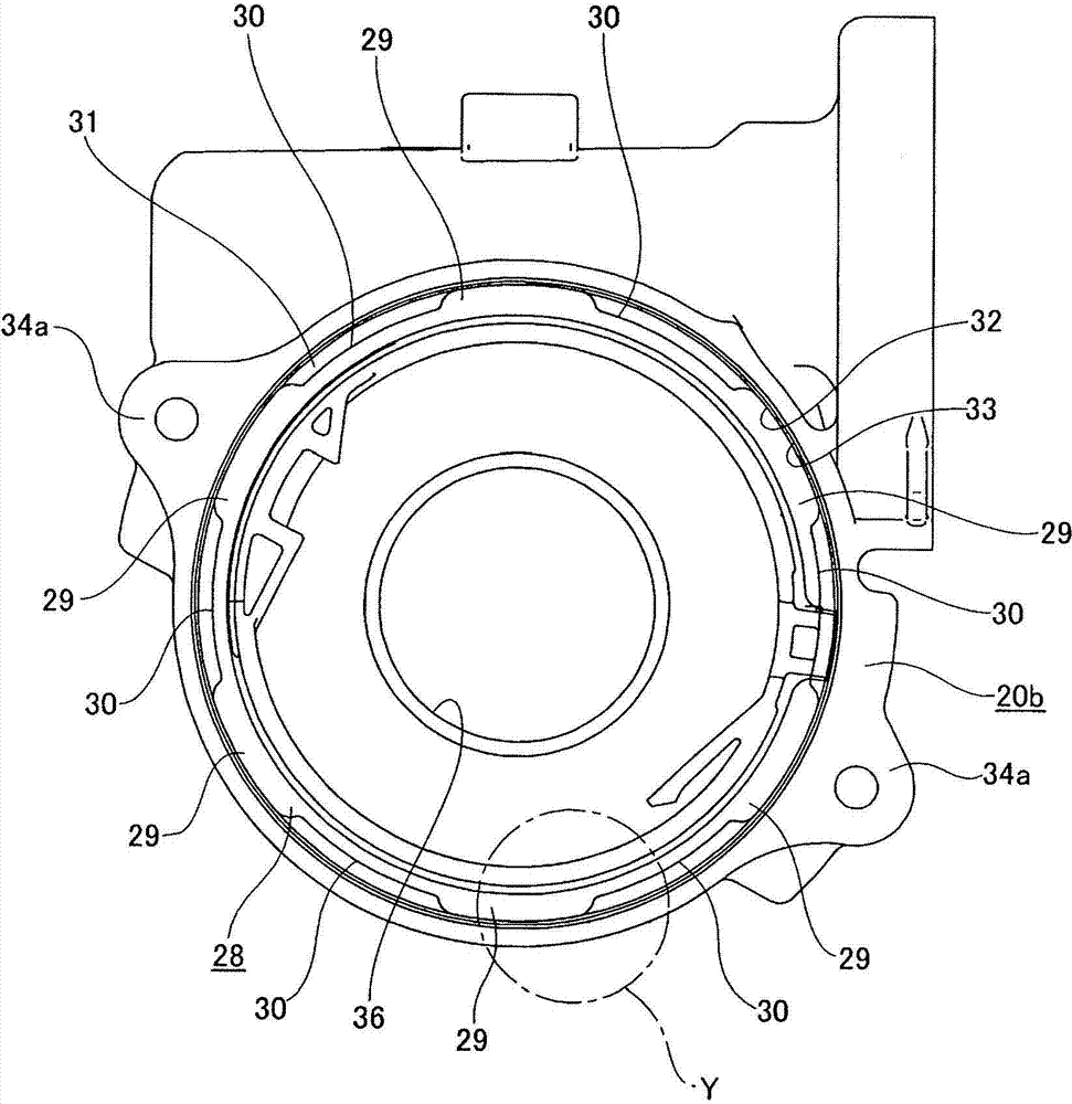
[0084] Figure 1-8 An electric power steering system according to a first embodiment of the present invention is shown. This electric power steering system includes an input shaft 12b, an output shaft 13b, and a housing 9 that supports both shafts so that the input shaft 12b and the output shaft 13b can rotate freely. The housing 9 is formed by combining the gear case 20b and the case cover 21b. The gear case 20b and the case cover 21b are respectively formed by, for example, die-casting using an aluminum alloy or injection molding using a high-performance resin. The input shaft 12b and the output shaft 13b have a hollow circular tube shape, and are connected by a torsion bar 11 in a state of being arranged concentrically with each other. That is, front and rear end portions of the torsion bar 11 are coupled to the front end portion of the output shaft 13b and the rear end portion of the input shaft 12b, respectively. The output shaft 13b is connected to the output shaft 3 ...


PUM


Abstract

This electric power-steering device has a first roller bearing and a second roller bearing that rotatably support an output shaft. The first roller bearing is provided between the outer peripheral surface of the output shaft and the inner peripheral surface of a through-hole of the gear housing. The second roller bearing is provided between the outer peripheral surface of the output shaft and the inner peripheral surface of an intermediate plate press-fitted into an opening in the gear housing. The outer peripheral edge of the intermediate plate has a shape in which large diameter parts and small-diameter parts are formed alternately, and the large-diameter parts are press-fitted into the gear housing.

Description

technical field [0001] The present invention relates to an electric power steering device that uses an electric motor as an auxiliary power source and reduces the driver's control force on a steering wheel. Background technique [0002] Such as Figure 20 As shown, in the steering device for automobiles, the rotation of the steering wheel 1 is transmitted to the input shaft 3 of the steering gear unit 2, and along with the rotation of the input shaft 3, a pair of pull rods 4 and 4 arranged on the left and right are pushed and pulled to feed the front wheels. Apply rudder angle. The steering wheel 1 is supported and fixed to a rear end portion of a steering shaft 5 . The steering shaft 5 is rotatably supported by the steering column 6 while penetrating the cylindrical steering column 6 in the axial direction. The front end of the steering column 6 is connected and fixed to accommodate a worm gear reducer 7 and a torque measuring instrument 8 (refer to Figure 21 ) etc. at ...

Claims


Application Information

Patent Timeline
Patent Type & Authority Applications(China)
IPC IPC(8): B62D5/04
CPCB62D5/0409B62D5/0403
Inventor 石井达也山本武士森山诚一
Owner NSK LTD
Learn More