

Combined clamp for online measuring of aero-engine blade processing
An aero-engine and combined technology, applied in the direction of manufacturing tools, metal processing equipment, measuring/indicating equipment, etc., can solve the problems of knife deformation and poor practicability, and achieve the effects of improving production efficiency and saving production costs
- Summary
- Abstract
- Description
- Claims
- Application Information
AI Technical Summary
Problems solved by technology
Method used
Image

Examples
Embodiment Construction
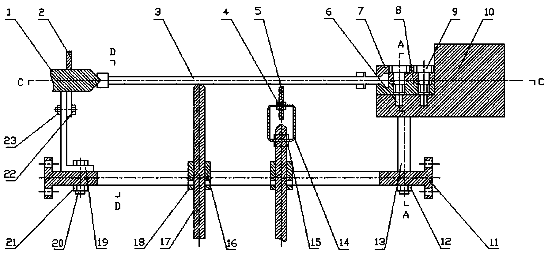
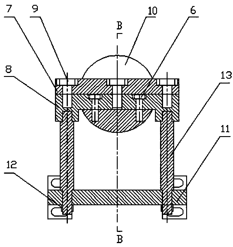
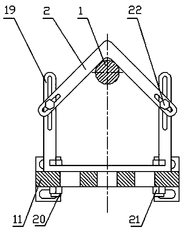
[0018] refer to Figure 1-5 . The combined fixture for on-line measurement of aeroengine blade processing in the present invention includes a tip 1, a tip hook 2, a blade 3, a first nut 4, a displacement sensor 5, a first screw 6, an upper tenon clamping module 7, and a tenon clamping lower module 8 , second screw 9, turntable clamping module 10, guide rail base 11, second nut 12, connecting screw 13, sensor adapter module 14, third nut 15, slider 16, support screw 17, slider fixing piece 18, The hook base 19 , the third screw 20 , the fourth nut 21 , the fourth screw 22 and the fifth nut 23 .
[0019] The guide rail base 11 is made up of four guide rails of rectangular cross-section, and two slide blocks 16 are housed on the guide rail base 11. Three support screws 17 are installed on the top, the top of the support screw 17 is hemispherical, and the bottom is a hexagonal groove. The height of the support screw 17 can be adjusted freely; The cooperation of the supporting s...
PUM
 Abstract
Description
Claims
Application Information