Robot and system for feeding and discharging high-pressure pipe joint parts and operation method implemented by robot and system

A technology of robots and pipe joints, which is applied in the field of machine tool loading and unloading devices and high-pressure pipe joint loading and unloading systems, which can solve the problems that cannot meet the production requirements of enterprises and the needs of front-line workers, workers cannot concentrate, and labor intensity is high. problems, to achieve the effect of enhancing system adaptability and flexibility, compact structure, and high transmission progress

Inactive Publication Date: 2014-07-09
NANTONG AMC MACHINERY
View PDF5 Cites 11 Cited by
  • Summary
  • Abstract
  • Description
  • Claims
  • Application Information

AI Technical Summary

Problems solved by technology

[0003] At present, ordinary machine tools are mostly used in the processing of small and medium-sized pipe joints, and the workers manually complete the loading, processing and unloading processes, which leads to high labor intensity for workers, low production efficiency, and long-term fatigue operations. Concentrate on, easy to produce waste products, and even cause personal injury
In addition, with the development of the economy, the demand for pipe joints in various industries has increased greatly, and the requirements for the working environment of front-line workers are also increasing. The traditional production mode can no longer meet the production requirements of enterprises and the needs of front-line workers.

Method used


Image

  • Robot and system for feeding and discharging high-pressure pipe joint parts and operation method implemented by robot and system
  • Robot and system for feeding and discharging high-pressure pipe joint parts and operation method implemented by robot and system
  • Robot and system for feeding and discharging high-pressure pipe joint parts and operation method implemented by robot and system

Examples


Embodiment Construction

[0053] The technical solution of the present invention will be described in detail below in conjunction with the accompanying drawings and specific embodiments.

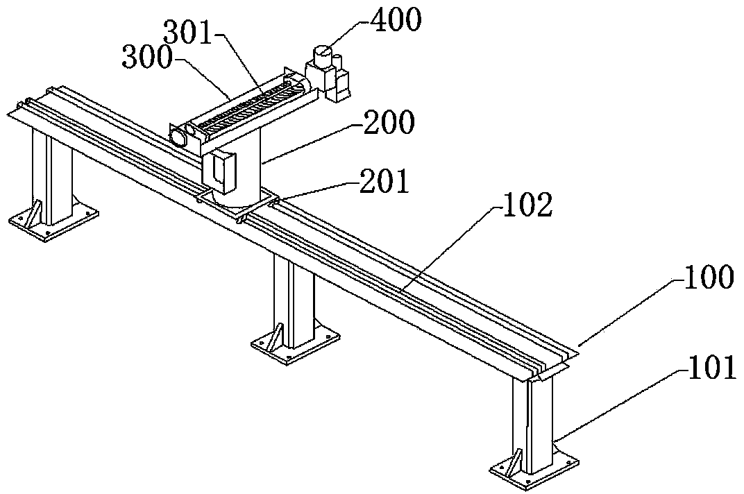
[0054] Such as figure 1 A loading and unloading robot for high-pressure pipe fittings is shown, including a base 100, a column 200, a support 300 and a machine head 400;

[0055] The base 100 is composed of a foot 101 and a ball guide rail 102 arranged on the top of the foot 101;

[0056] The column 200 is vertically arranged on the upper end of the ball guide rail 102, and the bottom of the column 200 is provided with a ball slider 201, which moves linearly along the ball guide rail 102 in the horizontal direction;

[0057] A support 300 perpendicular to the ball guide rail 102 and the column 200 is provided on the top of the column 200, a screw drive 301 is provided on the support 300, and the screw nut of the screw drive 301 is connected to the machine head 400;

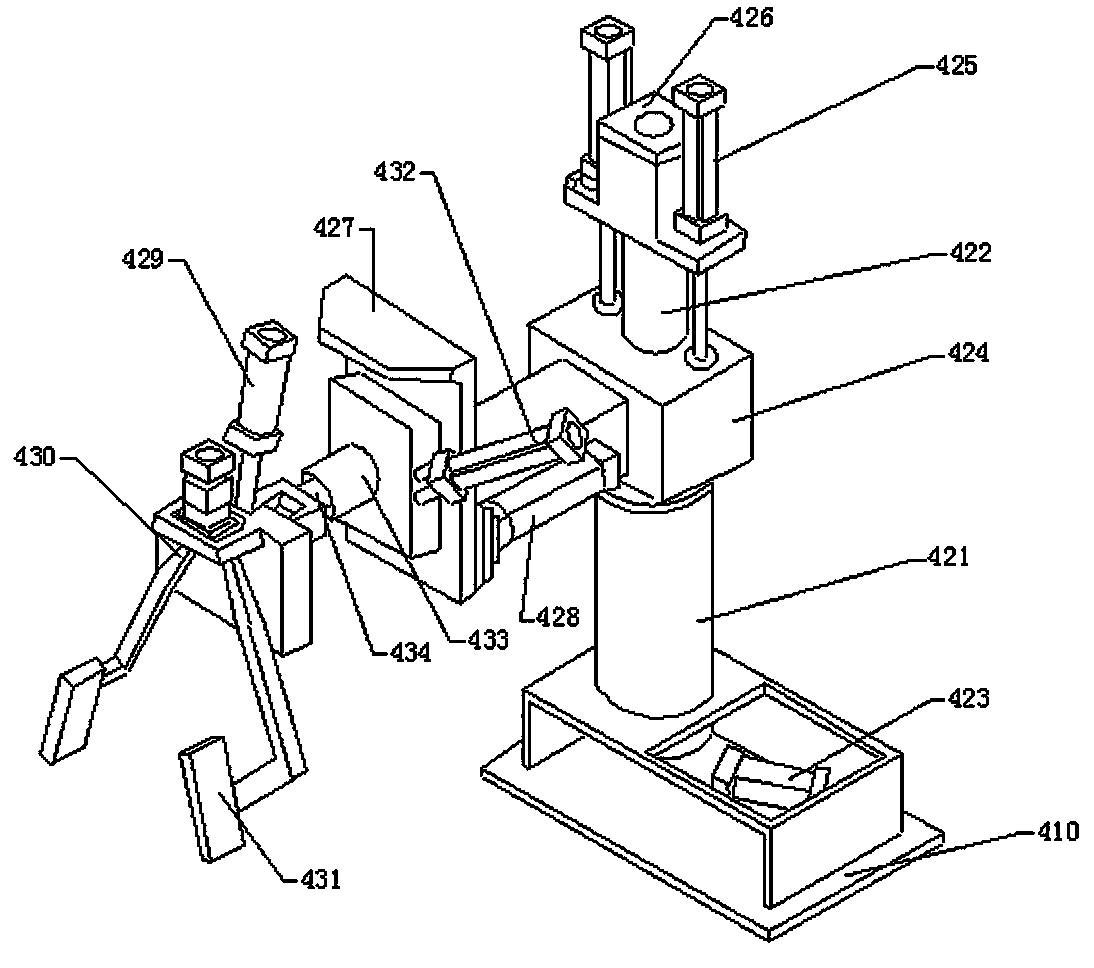
[0058] The machine head 400 includes a machine ...


PUM


Abstract

The invention discloses a robot for feeding and discharging high-pressure pipe joint parts. The robot comprises a base, an upright column, a support and a head. The base comprises legs and ball guide rails, and the ball guide rails are arranged on the upper portions of the legs, the upright column is vertically arranged at the upper ends of the ball guide rails, and ball sliders are arranged at the bottom of the upright column and horizontally and linearly move along the ball guide rails; the support which is respectively perpendicular to the ball guide rails and the upright column is arranged at the top of the upright column, a lead screw transmission gear is arranged on the support, and a lead screw nut of the lead screw transmission gear is connected with the head; the head comprises a seat and a feeding and discharging end actuator, and the feeding and discharging end actuator is mounted on the seat. The invention further discloses a system for feeding and discharging the high-pressure pipe joint parts. The robot and the system have the advantages that the system for feeding and discharging the high-pressure pipe joint parts is matched with a numerical-control machine tool, so that the high-pressure pipe joint parts can be automatically fed and discharged when switched over at machining stations in thread machining procedures, and automatic and unattended feeding and discharging effects can be realized in the machining procedures.

Description

technical field [0001] The invention belongs to the technical field of numerical control processing, and in particular relates to a loading and unloading device for machine tools, a loading and unloading system for high-pressure pipe joints, and a working method of the system. Background technique [0002] Machine tool loading and unloading robots are an emerging industry that has just emerged in China in recent years. However, in western developed countries, Japan and South Korea, as early as 20 years ago, loading and unloading robots have been widely used in various types of CNC machine tools . The combination of loading and unloading robots and CNC machine tools can realize all technological processes such as automatic grasping, loading, unloading, clamping, and processing of workpieces, which can greatly save labor costs and improve production efficiency. It is especially suitable for the processing and production of large quantities of small and medium-sized parts. ...

Claims


Application Information

Patent Timeline
Patent Type & Authority Applications(China)
IPC IPC(8): B23Q7/04
CPCB23Q7/04B23Q2707/04
Inventor 戚顺平冯克明
Owner NANTONG AMC MACHINERY
Why Eureka
Try Eureka