
A Method of Detecting Wear Pointer Using Internal Gear Coupling

A technology of internal meshing gears and couplings, applied in belts/chains/gears, spring mechanisms, transmission parts, etc., can solve the problems of difficult inspection, high labor intensity of maintenance workers, and difficult inspection and judgment. Demonstrate the effect of technological progress and avoid major equipment safety accidents

Active Publication Date: 2016-08-17
BAOSTEEL GROUP XINJIANG BAYI IRON & STEEL
View PDF4 Cites 0 Cited by
  • Summary
  • Abstract
  • Description
  • Claims
  • Application Information

AI Technical Summary

Problems solved by technology

[0003] It is not easy to check and judge the wear condition of the gear plate or spline of the low-speed output shaft of the crane lifting mechanism in daily equipment maintenance. Disintegration inspection, this method needs to position the vehicle, do not push the cart, use the electric hoist above the workshop to hoist the reel group, the high-altitude operation will cause high labor intensity for the maintenance workers, and the operation of high-altitude hoisting, dismantling and inspection of the ring gear matching parts has a greater impact on equipment maintenance personnel The unsafe factors also have a great impact on the normal production process. The two methods generally used are internal meshing forms; the wear of the mating surface has the disadvantage that it is not easy to check, and the gear can only be realized by disassembly. Inspection of surface wear; the originally designed hoisting mechanism of the bridge crane has no lubricating oil circuit in the matching part of the reel group, that is to say, the lubrication of the reel group ring gear can only be carried out during the regular disassembly inspection work, because There is no lubricating oil path, even if the tooth end surface is lubricated, the complete lubrication of the mating gear or the spline bearing surface cannot be achieved. The high temperature environment of the metallurgical enterprise steel plant and the loss of lubricating grease during use cause rapid wear of the meshing surfaces of the intermeshing gears main reason

Method used


Image

  • A Method of Detecting Wear Pointer Using Internal Gear Coupling
  • A Method of Detecting Wear Pointer Using Internal Gear Coupling
  • A Method of Detecting Wear Pointer Using Internal Gear Coupling

Examples


Embodiment

[0025] 1) Basis for gear wear:

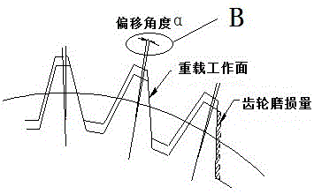
[0026] After the ring gear matched with the reel ring gear wears out, there will be a certain gap. During the operation of the reducer, a certain tooth of the low-speed output shaft of the reducer is used as the reference. It will deflect at a certain angle during the loading process. It is calculated through the corresponding relationship between the angle and the arc length. The ratio of the radii of the pitch circles is equal, (in the case of a small offset, the arc length can be regarded as a straight line), so the wear amount of the gear can be calculated.

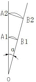
[0027] 2) Calculation of gear wear amount: After the ring gear of the reel ring gear is worn out, it will deflect at a heavy load. When the deflection angle α is a certain value, the arc lengths corresponding to different radii Calculated by formula:

[0028] A1B1=OA1*A2B2 / OA2

[0029] In the formula: the value of OA1 is equal to 1 / 2 of the diameter of the pitch circle of the meshin...


PUM


Abstract

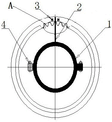
The invention provides a detection method for a wearing pointer through an inside-engaged gear coupling. A monitoring device is composed of a fixed snap ring, the wearing pointer, scale identification locating pieces and a connection bolt. A principle used in the invention is that the pointer shifts after wearing of the low-speed fluted disc of a speed reducer and the inner ring gear of a drum group and it is determined that a gear is worn or discarded when an upper set limit is reached. A calculation formula for the wear extent of the gear is expressed by the equation that A1B1 = OA2 * A1B1 / OA1, wherein the value of OA1 is 1 / 2 of the reference diameter of engaged internal and external gears, A2B2 refers to arc length corresponding to an angle alpha, A1B1 represents unknown wear extent, OA1 refers to the reference radius of the gear, and OA2- is distance between the measurement point of offset of the wearing pointer and the center of the gear reference circle.

Description

technical field [0001] The invention relates to a wear detection method in which a reel set of a hoisting mechanism of a hoisting machine is connected to a low-speed output shaft of a reducer and adopts meshing of internal and external gears. The method can carry out online detection of the wear status of gears in hidden parts, and is very accurate. Background technique [0002] At present, the connection and cooperation between the low-speed output shaft of the reducer and the reel group of the hoisting mechanism of the bridge crane usually adopts two methods: one is that the low-speed gear plate of the reducer (shaft end form is C-type) and the reel ring gear adopt internal and external gears. The direct connection method of meshing; the second is that the low-speed shaft spline of the reducer (shaft end form is H type) is connected with the reel group through the matching reel coupling. The reel coupling has a large bearing capacity and is automatic The advantages of adju...

Claims


Application Information

Patent Timeline
Patent Type & Authority Patents(China)
IPC IPC(8): B66C13/16B66D1/14F16H57/01
Inventor 李红熙丁佩司新军赵鹏滕永杰
Owner BAOSTEEL GROUP XINJIANG BAYI IRON & STEEL
Learn More