Horizontal rotating weft-guiding transmission mechanism for weaving machine

A technology of flat-spin weft insertion and transmission mechanism, applied in looms, textiles, textiles and papermaking, etc., can solve the problems of high production cost, high resistance and high processing requirements

Active Publication Date: 2014-07-09
JIANGSU YOUCHENG CNC TECH CO LTD
View PDF10 Cites 4 Cited by
  • Summary
  • Abstract
  • Description
  • Claims
  • Application Information

AI Technical Summary

Problems solved by technology

[0003] The first is to use conjugate cams, rotors, pendulum shafts, linkages, gear arms, transmission gears, etc. to achieve weft insertion. The disadvantages are that there are many parts involved in reciprocating motion, the cumulative gap error is large, and the free stroke is large during high-speed handover. It is not easy for the loom to run at high speed; the second is to use the cradle in the air to achieve weft insertion. Although there are fewer reciprocating parts involved in it, the weight of the cradle swing parts is heavy and the processing requirements are very high. The internal stress is large and the production cost is high. high, which is not convenient for mass production; the third is to use the screw to drive the weft insertion. Although there are not many transmission parts, the variable pitch processing of the screw requires very high processing requirements and high production costs. Because the screw uses sliding friction, the resistance is relatively large, and the cost of use is high, so it cannot be popularized in large quantities.

Method used


Image

  • Horizontal rotating weft-guiding transmission mechanism for weaving machine
  • Horizontal rotating weft-guiding transmission mechanism for weaving machine

Examples


Embodiment Construction

[0016] The present invention will be further described below in conjunction with accompanying drawing.

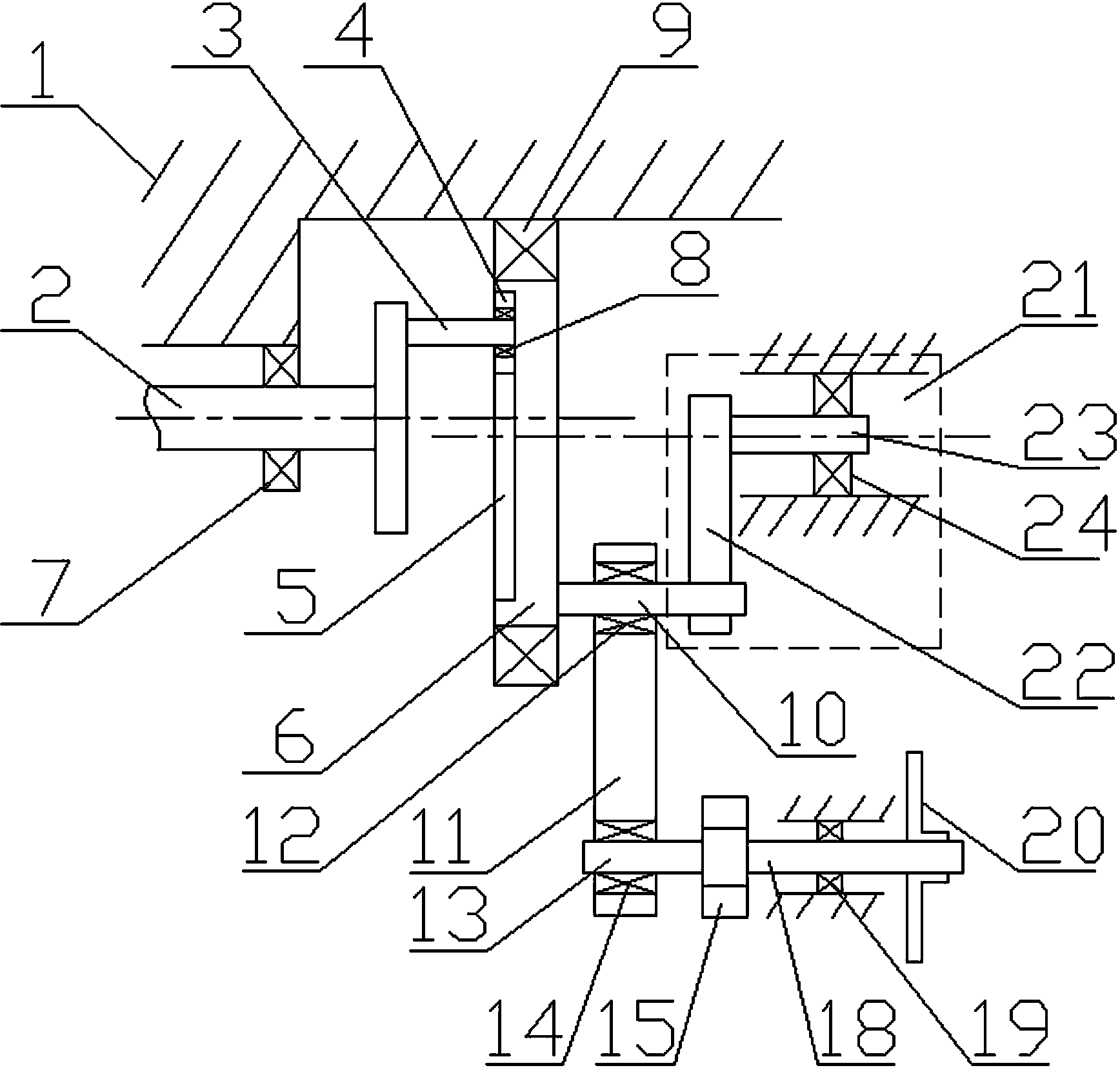
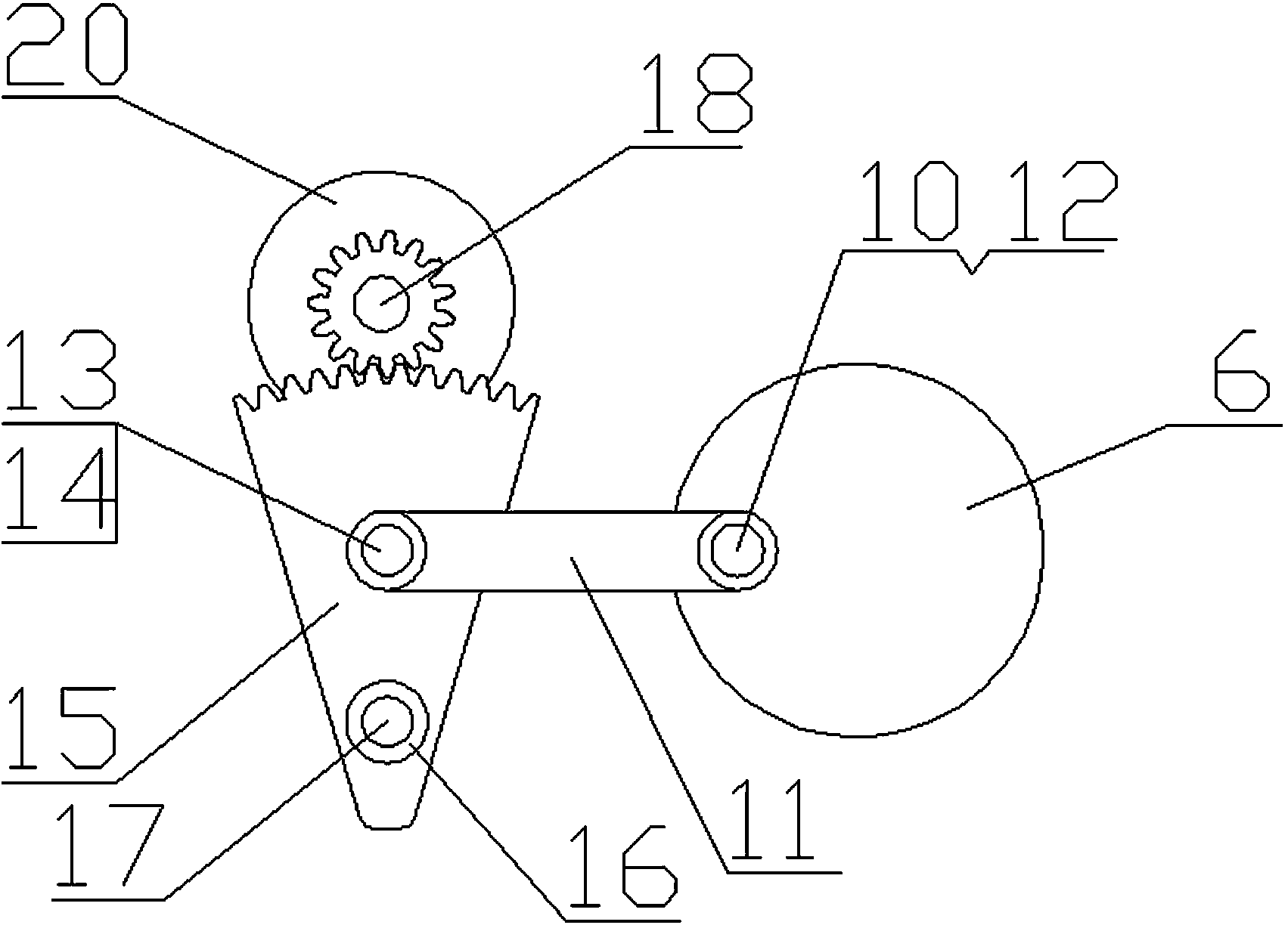
[0017] figure 1 , 2 As shown, a weft insertion transmission mechanism of a loom includes a frame 1, a driving shaft 2, a primary eccentric shaft 3, a driving roller 4, a chute 5, a passive disk 6, a driving shaft bearing 7, and a primary eccentric shaft. Shaft bearing 8, passive disk bearing 9, secondary eccentric shaft 10, weft insertion link 11, weft insertion link bearing 12, connection support shaft 13, fulcrum bearing 14, reciprocating tooth arm 15, tooth arm bearing 16, tooth arm Rotary support shaft 17, output gear shaft 18, output gear shaft bearing 19, transfer sword wheel 20 and secondary eccentric shaft stabilizing mechanism 21. The driving shaft 2 and the passive disk 6 are rotatable and parallel to the center lines of the circle, and the center lines are not on the same center. 3. The primary eccentric shaft 3 is socketed with the driving roller 4 through th...


PUM


Abstract

The invention relates to a horizontal rotating weft-guiding transmission mechanism for a weaving machine. A driving shaft and a driven plate are rotatably arranged on a rack; a primary core shifting shaft is fixed on an end surface of the driving shaft, and is connected with a driving roller through a primary core shifting shaft bearing in a sleeving manner; the driving roller extends in a chute in an end surface of the driven plate and applies force on a side wall of the chute; and when the driving shaft rotates by a circle, the driven plate can be driven by the primary core shifting shaft, the driving roller and the chute to rotate by a circle relative to the driving shaft under the condition that the speed ratio is changed. The transmission mechanism is simple and stable in structure; requirements on distribution of time and angles of a sword tape and a sword head inside and outside a weaving opening during weaving of the weaving machine can be met; the rigidity is high; connection transmission is soft; impact force is small; the movement trails of the sword tape and the sword head are effectively optimized; parts are machined simply; the cost and the inertia are low; the transmission mechanism is easy to repair; the production cost is saved; the running efficiency of the weaving machine is improved; and the number of reciprocating motion parts is small, so that high-speed running is facilitated.

Description

technical field [0001] The invention relates to a transmission mechanism of a textile machine, in particular to a loom flat-rotation weft insertion transmission mechanism for a rapier loom to drive a rapier belt to reciprocate. Background technique [0002] The high-speed rapier is fixed by the weft insertion transmission mechanism and the sley is separated by the conjugate cam beating-up structure, which is convenient for high-speed operation because of less moving parts and less inertia. At present, there are three typical weft insertion transmission mechanisms: [0003] The first is to use conjugate cams, rotors, pendulum shafts, linkages, gear arms, transmission gears, etc. to achieve weft insertion. The disadvantages are that there are many parts involved in reciprocating motion, the cumulative gap error is large, and the free stroke is large during high-speed handover. It is not easy for the loom to run at high speed; the second is to use the cradle in the air to achi...

Claims


Application Information

Patent Timeline
Patent Type & Authority Applications(China)
IPC IPC(8): D03D47/27
CPCD03D47/275
Inventor 王勇
Owner JIANGSU YOUCHENG CNC TECH CO LTD
Why Eureka
Try Eureka