
Anti-fatigue permanent magnetic vibration table

A vibrating table, fatigue-resistant technology, applied in the direction of fluid using vibration, etc., can solve the problems of large volume of permanent magnetic vibrating table, reduced service life, easy damage of spring leaf, etc., to reduce the limitation of freedom, improve service life, and enhance reliability effect

Active Publication Date: 2014-06-04
YMC PIEZOTRONICS
View PDF6 Cites 1 Cited by
  • Summary
  • Abstract
  • Description
  • Claims
  • Application Information

AI Technical Summary

Problems solved by technology

The volume of the permanent magnet vibrating table in the prior art is relatively large, the spring piece is arranged on the top or bottom of the vibrating column, and one end is positioned. After a period of use, the movement track of the vibrating column will change. The spring piece and the vibrating column are connected in a fixed way. The vibration resistance is too large, which generates more heat and reduces the service life. The fixed connection between the spring piece and the vibration column makes the spring piece easily damaged

Method used


Image

  • Anti-fatigue permanent magnetic vibration table
  • Anti-fatigue permanent magnetic vibration table

Examples


Embodiment Construction

[0015] Below in conjunction with accompanying drawing and specific embodiment, further illustrate the present invention, it should be understood that these embodiments are only used to illustrate the present invention and are not intended to limit the scope of the present invention, after reading the present invention, those skilled in the art will understand various aspects of the present invention Modifications in equivalent forms all fall within the scope defined by the appended claims of this application.

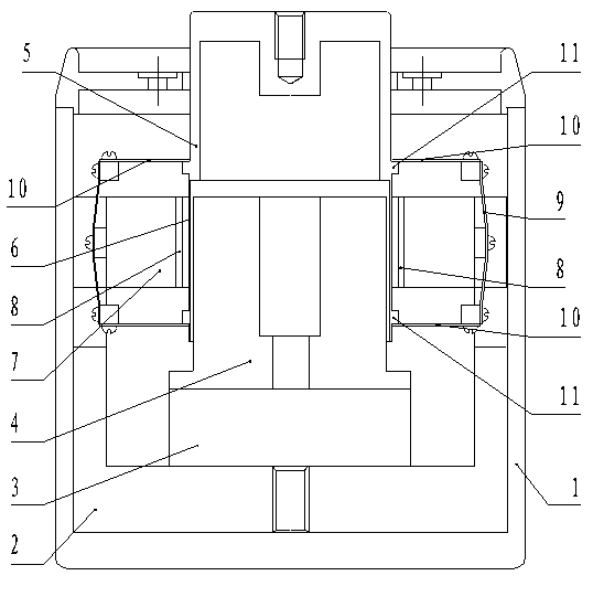
[0016] Such as figure 1 A kind of anti-fatigue permanent magnet vibrating table shown, comprises outer cover 1, and housing 2 is installed on the bottom of outer cover, and NdFeB permanent magnet 3 is installed on the upper side of housing, and NdFeB permanent magnet is installed on NdFeB permanent magnet. The coaxial magnetic core 4 is sleeved with a coaxial vibrating column 5 in the outer gap of the magnetic core 4. The vibrating column 5 protrudes outside the outer c...


PUM


Abstract

The invention discloses an anti-fatigue permanent magnetic vibration table which comprises an outer cover. A permanent magnet is arranged at the bottom of the outer cover and provided with a magnet core. A vibration column is connected with a gap outside the magnet core in a sleeved mode and extends out of the outer cover. An electromagnetic coil is arranged outside the position, coinciding with the magnet core, of the bottom of the vibration column. A support fixed to the outer cover is connected with a gap outside the vibration column in a sleeved mode. Vertical spring pieces which are vertically arranged are evenly distributed on the periphery of the support. The two ends of the vertical spring pieces are connected with horizontal spring pieces. The two layers of horizontal spring pieces are connected with an upper step arranged outside the vibration column and a lower step arranged outside the vibration column in a lap joint mode. The spring pieces are connected with the vibration column in a lap joint mode, and therefore resistance of the spring pieces to the vibration column is reduced, generated heat is reduced, limitation on the freedom degree of the spring pieces is reduced as well, and the service life of the spring pieces is prolonged; the two layers of horizontal spring pieces well guide the vibration column, and therefore the moving track of the vibration column is stable, and the service life of the vibration table is prolonged.

Description

technical field [0001] The patent of the present invention relates to a vibrating table, in particular to a fatigue-resistant permanent magnet vibrating table. Background technique [0002] The vibrating table (vibrator) is a device attached to certain machinery and equipment to generate excitation force, and is an important part that utilizes mechanical vibration. The vibrator can make the excited object obtain a certain form and size of vibration, so as to perform vibration and strength tests on the object, or to calibrate vibration testing instruments and sensors. The vibrating table can also be used as an exciting part to form a vibrating machine to realize the conveying, screening, compacting, forming and tamping of soil and gravel for materials or objects. The vibrating table can generate unidirectional or multidirectional, simple harmonic or non-harmonic excitation force. [0003] The domestic research on the permanent magnet vibration table (vibrator) began in the ...

Claims


Application Information

Patent Timeline
IPC IPC(8): B06B1/08
Inventor 陈启山田自生
Owner YMC PIEZOTRONICS
Learn More