Eureka AIR delivers breakthrough ideas for toughest innovation challenges, trusted by R&D personnel around the world.

Temperature-difference power conversion method

A technology of power conversion and power conversion system, which is applied in the directions of mechanisms, machines/engines, and mechanical equipment that generate mechanical power to achieve the effects of simple structure, cost control, and wide sources.

Inactive Publication Date: 2014-07-09
马照龙
View PDF6 Cites 3 Cited by
  • Summary
  • Abstract
  • Description
  • Claims
  • Application Information

AI Technical Summary

Problems solved by technology

[0002] As far as I know, the current thermal power system needs to exchange materials with the outside world. For example, a car needs to inhale oxygen and emit carbon dioxide, and it needs to be heated at a high temperature to drive it. For example, a thermal power steam turbine has the advantage of fast operation speed, and the point of release is the emission. High-temperature product carbon dioxide, I think this is a misunderstanding of energy utilization

Method used


Image

  • Temperature-difference power conversion method

Examples


Embodiment Construction

[0010] The method invention will be further described below in conjunction with the accompanying drawings.

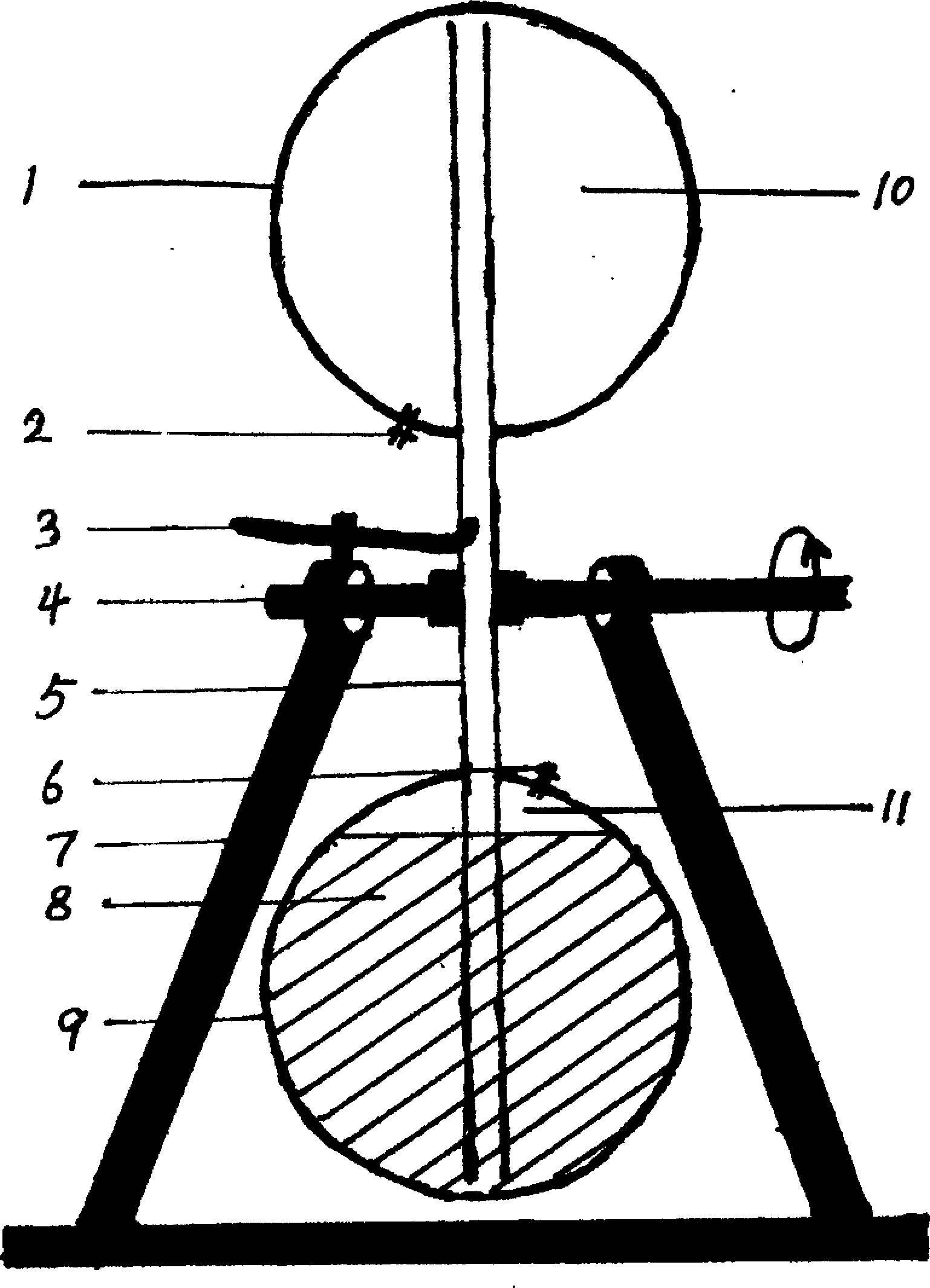
[0011] The attached drawing is a brief structural diagram of the thermodynamic power conversion system (note: the shape shown in the attached drawing is not the actual shape, and is only used to facilitate the understanding of the working process of the conversion system): 1 and 9 are closed containers connected to each other; 2 and 6 are closed valves; 3 is a bias positioning device; 4 is a bearing; 5 is a pipe; 7 is a bracket; 8 is a working fluid; 10, 11 are relatively independent saturated steam; The core component of thermoelectric power conversion. Now briefly describe its temperature difference power conversion process as shown in the accompanying drawings, when the two containers of 1 and 9 have no temperature difference, the working medium is in a static state in the 9 container. When heating the container 9, the heat is transferred to the working fluid 8, and...


PUM


Abstract

The invention discloses a temperature-difference power conversion method and belongs to the technical field of the steam generation methods. The method is capable of realizing power output based on normal-state temperature difference; the following technical proposal is adopted: a temperature-difference power conversion core component in a temperature-difference power conversion system is manufactured by use of a method of vacuumizing first and then injecting a volatile liquid as a working medium in the manufacturing process; temperature difference acquisition is carried out by use of a guide method, a replacement method and a direct contact method and the temperature difference acquired is enabled to act on the temperature-difference power conversion core component so as to realize power output of the temperature-difference power conversion system; the temperature-difference power conversion method is mainly used for power output or converting the power into electric energy and then transmitting the electric energy to electricity users.

Description

technical field [0001] The invention relates to a method for realizing power output by using the difference between high and low temperatures, which belongs to the technical field of steam generation methods, and more specifically uses the steam generation method to realize power output. Background technique [0002] As far as I know, the current thermal power system needs to exchange materials with the outside world. For example, a car needs to inhale oxygen and emit carbon dioxide, and it needs to be heated at a high temperature to drive it. For example, a thermal power steam turbine has the advantage of fast operation speed, and the point of release is the emission. High temperature produces carbon dioxide. I think this is a misunderstanding of energy utilization. In fact, the closed system and normal temperature difference energy exchange can be used to achieve power output and reduce or avoid additional carbon emissions. Contents of the invention [0003] The purpose...

Claims


Application Information

Patent Timeline
Patent Type & Authority Applications(China)
IPC IPC(8): F03G7/04
Inventor 马照龙
Owner 马照龙
Why Eureka
Eureka Blog
Learn More