Supercharge Your Innovation With Domain-Expert AI Agents!

Optical lens zoom drive mechanism of stage lamp

A technology of optical lens and transmission mechanism, which is applied in the field of stage lights, can solve the problems of not being able to meet customers' quiet requirements, affect the use effect, and high maintenance costs, and achieve the effects of low noise, convenient adjustment, and low maintenance rate

Active Publication Date: 2014-07-09
福建吉艾普光影科技有限公司
View PDF4 Cites 1 Cited by
  • Summary
  • Abstract
  • Description
  • Claims
  • Application Information

AI Technical Summary

Problems solved by technology

At present, in the lighting industry, in order to achieve the purpose of zooming the optical lens assembly of stage lights through lifting and linear zooming, linear motors are used as the driving power source; however, there are many problems in the use of linear motors, such as: it cannot be avoided During the working process, due to the problems of the motor itself, the vibration in the radial direction is caused, especially when the linear motor is working close to the end, the vibration is the largest, resulting in a large vibration in different directions in the projected light spot during the optical zoom process. Affect the use effect; at the same time, the linear motor will generate a lot of noise during work, especially the noise generated during work will be amplified in the relatively closed space of the product. If multiple products work at the same time, the noise generated will not be able to Meet the customer's silent requirements for the product; in addition, the cost of linear motors is much higher than that of stepping motors. In terms of the products mentioned in this case, the total cost of linear motors is twice that of stepping motors, and the use of The current structure design, the service life of the product is short, and the follow-up maintenance cost is high

Method used


Image

  • Optical lens zoom drive mechanism of stage lamp
  • Optical lens zoom drive mechanism of stage lamp
  • Optical lens zoom drive mechanism of stage lamp

Examples


specific Embodiment approach

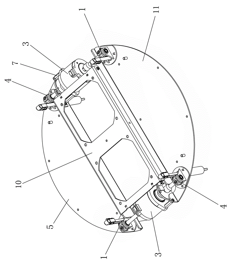
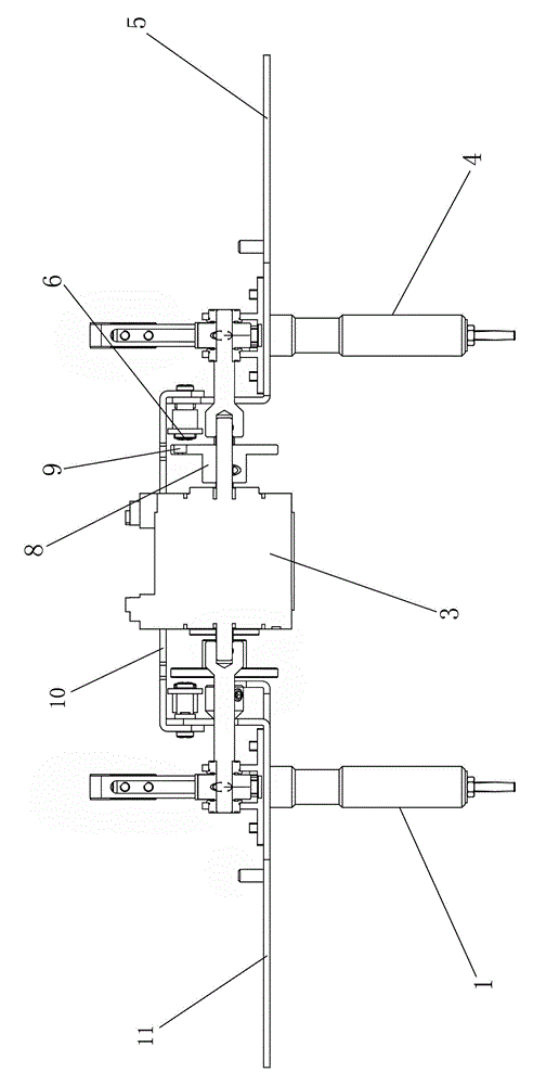
[0019] Such as figure 1 , figure 2 As shown, an optical lens zooming transmission mechanism of a stage lamp comprises a left fixed plate 5 and a right fixed plate 11, and the left fixed plate 5 and the right fixed plate 11 are connected by a fixed reinforcing plate 10; the structure of the right fixed plate 11 It is symmetrical to the structure of the left fixed plate 5; the left and right sides of the left fixed plate 5 are respectively connected with the left linear transmission mechanism 1 and the right linear transmission mechanism 4; the left and right sides of the right fixed plate 11 are respectively connected with the right linear transmission mechanism 4 and the left linear transmission mechanism The transmission mechanism 1; the left linear transmission mechanism 1 and the right linear transmission mechanism 4 are respectively connected with the biaxial stepping motor 3; the biaxial stepping motor 3 is connected to the left fixed plate 5 through the hexagonal column...


PUM


Abstract

The invention discloses an optical lens zoom drive mechanism of a stage lamp. The optical lens zoom drive mechanism comprises a left fixing plate and a right fixing plate which are connected through a fixing reinforcing plate. The left fixing plate and the right fixing plate are structurally symmetrical. The left and right sides of the left fixing plate are connected with a left linear drive mechanism and a right linear drive mechanism respectively. The left and right sides of the right fixing plate are connected with the right linear drive mechanism and the left linear drive mechanism respectively. Each of the left linear drive mechanism and the right linear drive mechanism is connected with a dual-axis stepping motor. The dual-axis stepping motors are connected on the left fixing plate. A magnet flange is arranged between each dual-axis stepping motor and the right linear drive mechanism. A magnet is connected on each magnet flange, and the inner side of the left fixing plate is connected with magnetic induction circuit boards which are just located on the outer sides of the corresponding magnets. The optical lens zoom drive mechanism is simple in structure, convenient to operate and adjust, and practical.

Description

technical field [0001] The invention relates to the field of stage lights, in particular to an optical lens zoom transmission mechanism for stage lights. Background technique [0002] At present, the existing stage lights need to realize the zooming of the light output of the light, and realize the zooming of the light output through an ordinary belt transmission device (a combination of a motor, a transmission wheel, a transmission belt, and a tensioning device) or a linear motor. At present, in the lighting industry, in order to achieve the purpose of zooming the optical lens assembly of stage lights through lifting and linear zooming, linear motors are used as the driving power source; however, there are many problems in the use of linear motors, such as: it cannot be avoided During the working process, due to the problems of the motor itself, the vibration in the radial direction is caused, especially when the linear motor is working close to the end, the vibration is th...

Claims


Application Information

Patent Timeline
IPC IPC(8): F21V14/06
Inventor 林啸郭进东马福
Owner 福建吉艾普光影科技有限公司
Features
  • R&D
  • Intellectual Property
  • Life Sciences
  • Materials
  • Tech Scout
  • Unparalleled Data Quality
  • Higher Quality Content
  • 60% Fewer Hallucinations
Learn More