
Vertical sintering furnace

A sintering furnace and vertical technology, applied in the field of sintering furnaces, can solve the problems of non-reuse of heat, affect the normal work of workers, and occupy a large space for equipment, so as to shorten the firing time, improve the utilization rate of heat, and occupy less space Effect

Inactive Publication Date: 2014-07-09
HUZHOU KEFU ELECTRONICS TECH
View PDF8 Cites 7 Cited by
  • Summary
  • Abstract
  • Description
  • Claims
  • Application Information

AI Technical Summary

Problems solved by technology

The sintering equipment commonly used in the prior art includes tunnel-type sintering kiln, ladle furnace and nitrogen kiln. Among them, the tunnel-type sintering kiln generally includes a long linear tunnel, and the kiln car runs on the track laid at the bottom, and the combustion equipment is located in the The two sides of the middle part of the tunnel kiln directly heat the materials in the kiln, mainly including the preheating area, debinding area, low temperature area, high temperature area and heat dissipation area. The equipment occupies a large space and the heat is lost quickly, especially for manganese-zinc iron When the oxygen core is sintered, it needs to be quenched by air. The heat after the sintering of the magnetic core is directly discharged in the workshop, which leads to an increase in the ambient temperature of the workshop and affects the normal work of the workers. Moreover, the heat is not reused, resulting in a waste of resources.

Method used


Image

  • Vertical sintering furnace
  • Vertical sintering furnace
  • Vertical sintering furnace

Examples


Embodiment

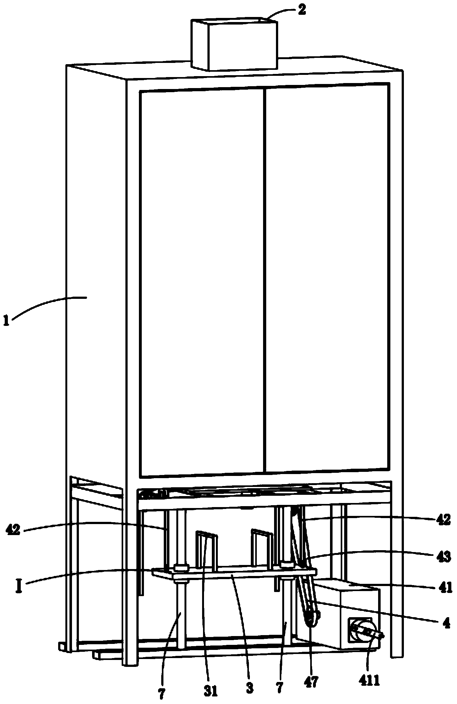
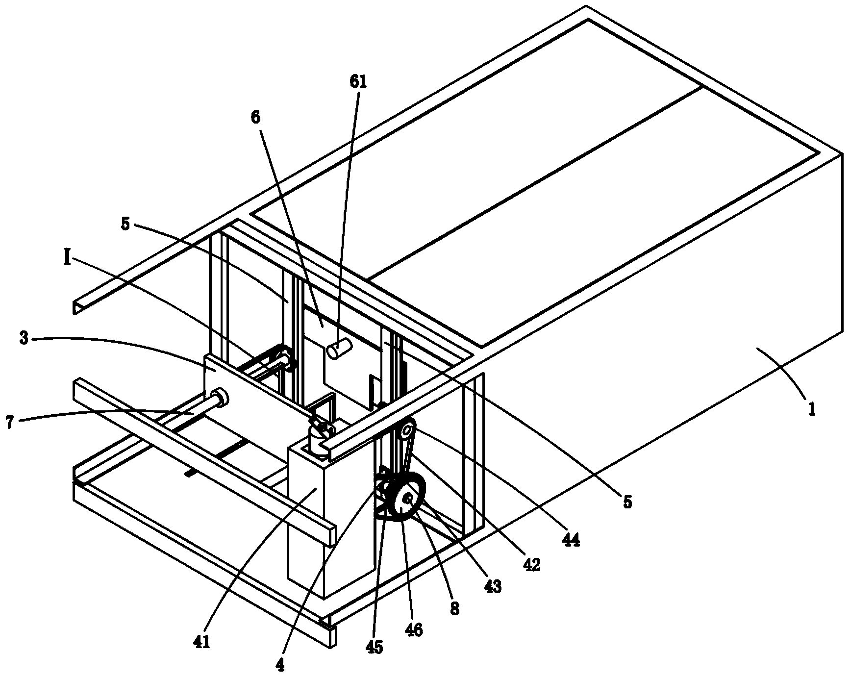
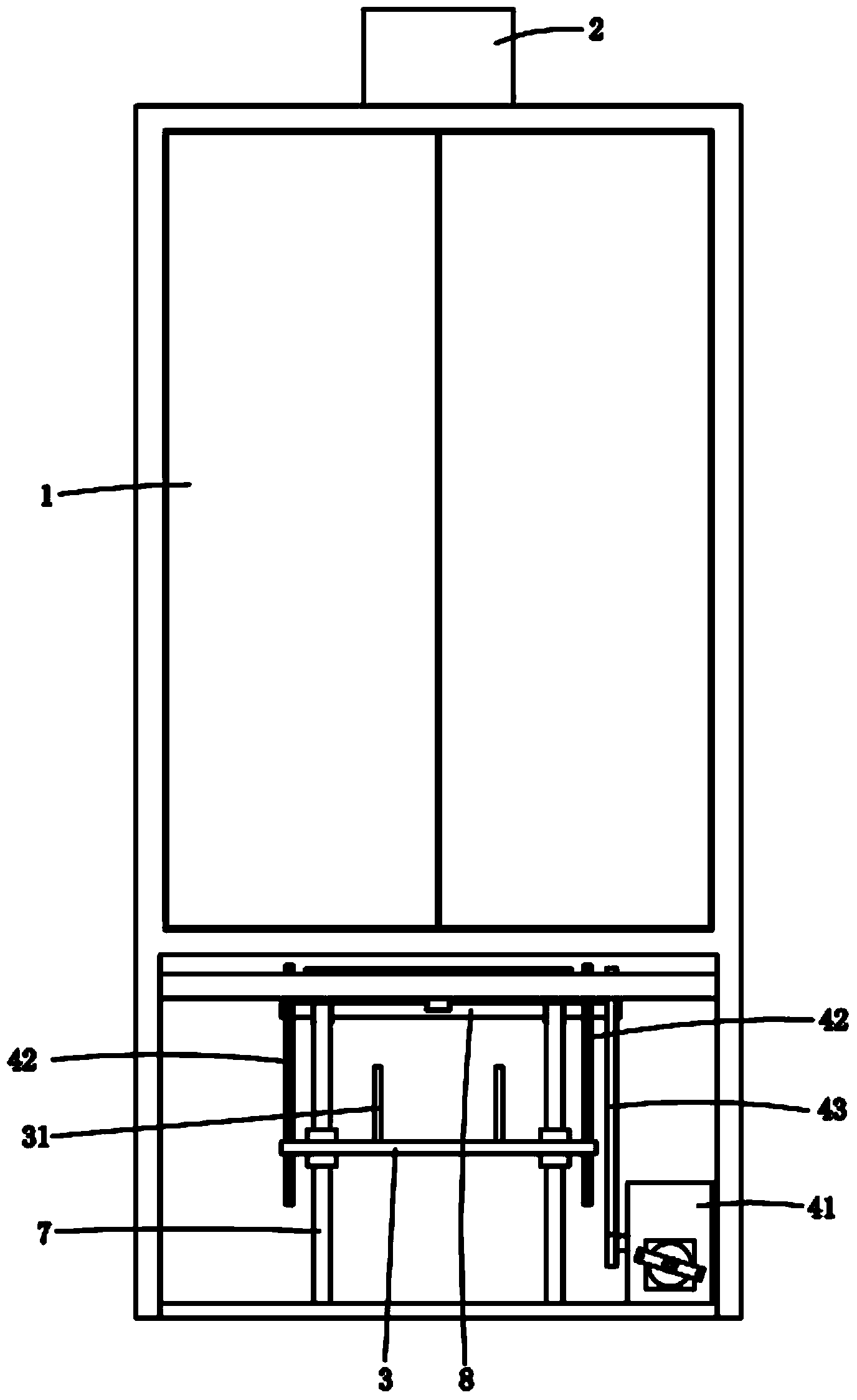
[0019] as attached Figure 1 to Figure 5 As shown, a vertical sintering furnace includes a sintering furnace 1 whose inner wall is covered with a heat insulating material and a heating channel 2, the heating channel 2 is arranged in a furnace hearth opened along the vertical direction of the sintering furnace 1, and the heating channel 2 runs through the entire furnace; the upper end of the heating channel 2 is a material inlet, and the lower end is a material outlet. The bearing fixtures of the blanks are neatly discharged up and down in the heating channel 2 for sintering; the discharge device I is provided under the sintering furnace 1, and the discharge device I includes a carrier plate 3 and a lifting mechanism 4, and the two sides of the discharge port are symmetrically arranged. There are slide rails 5, on which a baffle plate 6 is matched and connected, and the baffle plate 6 moves back and forth in the slide rail 5, and a column 7 is fixed at the bottom of the slide r...


PUM


Abstract

The invention relates to a vertical sintering furnace. The vertical sintering furnace comprises a sintering furnace body and a heating passage, wherein a heat insulating material covers the inner walls of the sintering furnace body, the heating passage is arranged in a hearth arranged along the vertical direction of the sintering furnace body and penetrates through the whole hearth, the upper end of the heating passage is a feeding port while the lower end of the same is a discharging port, loading clamps for loading green magnetic cores are vertically and neatly arranged in the heating passage for sintering, a discharging device is arranged below the sintering furnace body and comprises a carrying plate and a lifting mechanism, slide rails are symmetrically arranged on two sides of a discharging port, a stop plate is connected onto the slide rails in a matched manner, a vertical column is fixed at the bottom of each slide rail, and the carrying plate sleeves the vertical columns. By means of repeatedly utilizing heat from bottom to top, sintering time is effectively shortened, sintering efficiency is effectively improved, energy consumption is saved, and production cost is reduced.

Description

technical field [0001] The invention relates to a sintering furnace, in particular to a vertical sintering furnace for magnetic core sintering. Background technique [0002] A magnetic core refers to a sintered magnetic metal oxide composed of various iron oxide mixtures, for example, manganese-zinc ferrite and nickel-zinc ferrite are typical magnetic core body materials, usually used in various electronic devices coils and transformers. Usually, in the production process of the magnetic core, it is necessary to put the pressed and cut-shaped magnetic core into a sintering furnace for sintering to improve the performance of the magnetic core and meet the needs of the application. The sintering equipment commonly used in the prior art includes tunnel-type sintering kiln, ladle furnace and nitrogen kiln. Among them, the tunnel-type sintering kiln generally includes a long linear tunnel, and the kiln car runs on the track laid at the bottom, and the combustion equipment is loc...

Claims


Application Information

Patent Timeline
Patent Type & Authority Applications(China)
IPC IPC(8): F27B1/00F27B1/21H01F41/02
Inventor 周继军
Owner HUZHOU KEFU ELECTRONICS TECH
Learn More